Optical engine assembly equipment and assembly method

A technology for assembling equipment and light engines, which is applied to mechanical equipment, devices for coating liquid on surfaces, connecting components, etc., which can solve the problems of poor matching accuracy and cumbersome assembly operations, and achieve high position matching accuracy and convenient assembly operations. Effect

Pending Publication Date: 2022-07-29
江西联坤智能科技有限公司
View PDF0 Cites 1 Cited by
  • Summary
  • Abstract
  • Description
  • Claims
  • Application Information

AI Technical Summary

Problems solved by technology

[0006] In order to solve the above-mentioned technical problems, the present invention provides an optical engine assembly equipment and assembly method, by adopting the multi-degree-of-freedom combination of the first adjustment mechanism, the second adjustment mechanism, the first operation table, the second operation table and the mounting frame And high-precision adjustment methods, solve the problems of poor position matching accuracy and cumbersome assembly operations of micro-display chips, color-combining prisms, and imaging lenses in existing light engine assembly equipment

Method used


Image

  • Optical engine assembly equipment and assembly method
  • Optical engine assembly equipment and assembly method
  • Optical engine assembly equipment and assembly method

Examples


Embodiment 1

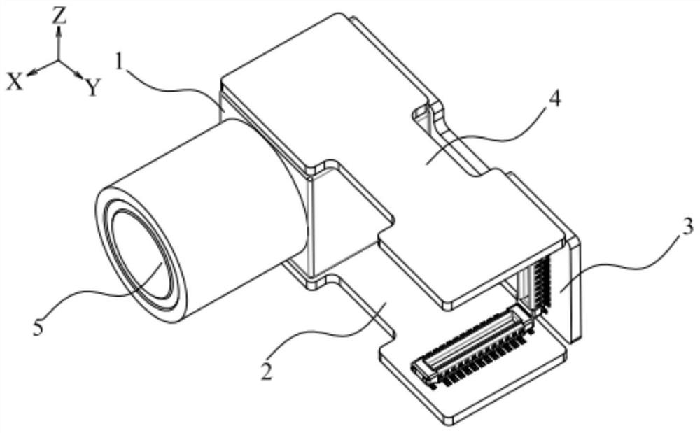
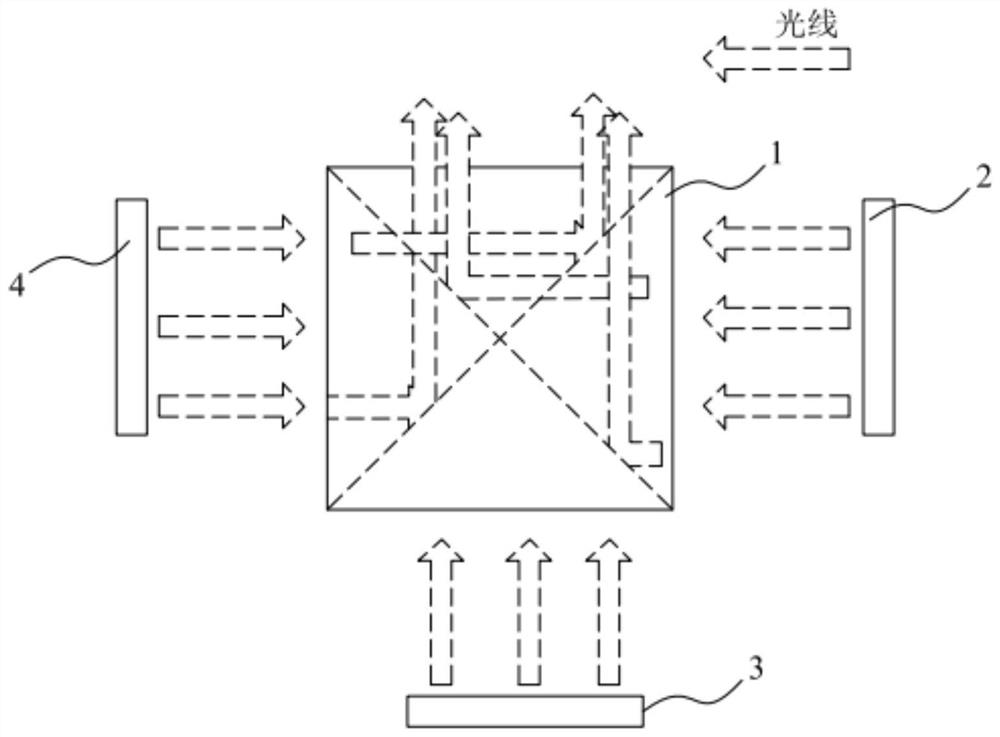
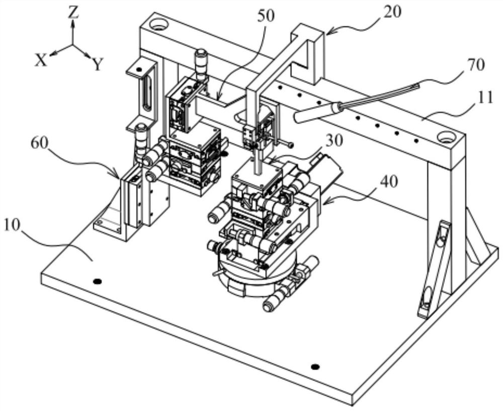
[0066] This embodiment provides a light engine assembling equipment, the light engine structure to be assembled is as follows figure 1 shown. The light engine includes a color combination prism 1 , a first micro display chip 2 , a second micro display chip 3 , a third micro display chip 4 , and an imaging lens 5 respectively mounted on the color combination prism 1 . The color combination prism 1 has a hexahedral structure, the first micro display chip 2 and the third micro display chip 4 are respectively located on opposite sides of the color combination prism 1, and the second micro display chip 3 and the imaging lens 5 are respectively located on the color combination prism 1. In addition, the other two opposite sides of the color combination prism 1 are used as the clamping surfaces for clamping the color combination prism 1 during the assembly process of the light engine. In the specific implementation process, the first micro display chip 2 , the second micro display ch...

Embodiment 2

[0097] The difference between this embodiment and Embodiment 1 is that the assembled light engine has two micro display chips, and the corresponding fitting portion includes a first clamping member and a second clamping member. During specific implementation, the two clamping members enclose an L-shaped structure.

Embodiment 3

[0099] The difference between this embodiment and Embodiment 1 is that the assembled light engine has a micro display chip, and the corresponding attaching part includes a first clamping member. The first clamping member is arranged corresponding to the position where the color combination prism needs to be installed with the micro display chip.


PUM


Abstract

The invention discloses optical engine assembly equipment and an assembly method. The equipment comprises a workbench, a mounting frame, a first adjusting mechanism, a first operation table, a second adjusting mechanism and a second operation table. The color combination prism is adjusted through a second adjusting mechanism, so that the imaging lens corresponds to the position of the output surface of the color combination prism; after the first operation table clamps the micro display chip which is dispensed on the periphery and electrified, an image sensor collects an image so as to adjust the first adjusting mechanism to carry out active alignment on the micro display chip and the imaging lens, and then curing and separating are carried out; the color combination prism provided with the micro display chip is far away from the imaging lens, glue dispensing is conducted on the output face of the color combination prism, images are collected through the image sensor so that the second adjusting mechanism can be adjusted to conduct active alignment of the color combination prism provided with the micro display chip and the imaging lens, then solidification and separation are conducted, and assembling of the optical engine is completed. According to the optical engine, high position matching precision among the micro display chip, the color combination prism and the imaging lens in the optical engine can be ensured, and the assembly operation is convenient.

Description

technical field [0001] The invention belongs to the technical field of light engine packaging, and in particular relates to an optical engine assembling device and an assembling method for assembling an optical engine by using the light engine assembling device. Background technique [0002] In recent years, with the advent of microdisplay chip technology, miniaturized and high-resolution projection display has become possible. Large field of view, high imaging quality, small size, and wearable micro-projection light engines are getting more and more attention, especially in today's key development of augmented reality (AR), near-eye display (Near-eye display, NED for short) and optical fields such as wearables. [0003] The miniature projection light engine in the prior art is the most critical component in the projection imaging system; among them, in order to realize the color display, the miniature projection light engine usually adopts a color combination device such a...

Claims


Application Information

Patent Timeline
IPC IPC(8): F16B11/00B05C5/02B05C13/02B05C11/00B05D1/26B05D3/02
CPCF16B11/006B05C5/0212B05C13/02B05C11/00B05D1/26B05D3/0254
Inventor 汤善祥周子彬胡洪程余成龙林竞
Owner 江西联坤智能科技有限公司
Why Eureka
Try Eureka