Automatic glazing device for ceramics
An automatic glazing device and ceramic technology, which is applied in the direction of ceramic forming machines, manufacturing tools, auxiliary forming equipment, etc., can solve the problems of low efficiency and high price of manual ceramic glazing, and achieve the effect of convenient automatic picking and placing of ceramics
- Summary
- Abstract
- Description
- Claims
- Application Information
AI Technical Summary
Problems solved by technology
Method used
Image

Examples
Embodiment 1
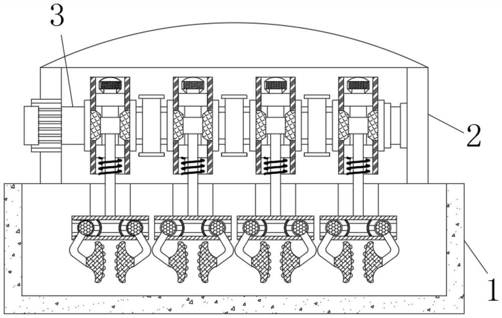
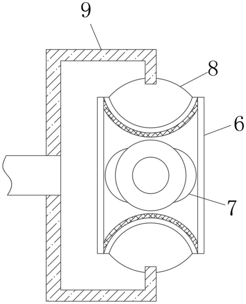
[0027] see Figure 1-3 , a ceramic automatic glazing device, comprising a liquid tank 1, the upper end of the liquid tank 1 is fixedly installed with a support frame 2, the interior of the support frame 2 is rotatably connected with a rotating roller 3, and the rotating roller 3 is between the linkage mechanism 4. A connecting frame 6 is fixedly installed on the end face, a rotating wheel 7 is connected to the rotation of the connecting frame 6, a connecting bag 8 is fixedly installed on the upper and lower ends of the rotating wheel 7, and a connecting pipe 9 is fixedly installed on the opposite back of the connecting bag 8, and the rotating The roller 3 is fixedly installed with a connecting frame 6 on the end face between the linkage mechanism 4. The rotation of the connecting frame 6 is connected with a rotating wheel 7, and the upper and lower ends of the rotating wheel 7 are fixedly installed with a connecting bag 8. The opposite back of the connecting bag 8 The connecti...
Embodiment 2
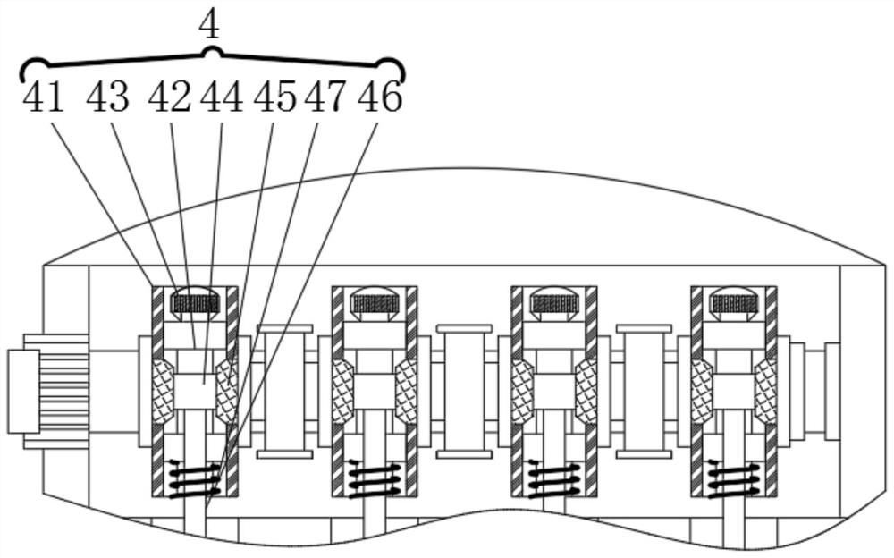
[0030] see figure 1 , 4 5. An automatic glazing device for ceramics, comprising a liquid tank 1, a support frame 2 is fixedly installed on the upper end of the liquid tank 1, a rotating roller 3 is rotatably connected inside the support frame 2, and a rotating roller 3 is fixedly installed inside the The evenly distributed linkage mechanism 4, the liquid holding tank 1 is provided with a clamping mechanism 5, and the clamping mechanism 5 includes: a connecting plate 51, and a connecting groove 52 is opened inside the connecting plate 51, and the left and right ends of the connecting groove 52 are slidable. An arc-shaped plate 53 is connected, the opposite sides of the arc-shaped plate 53 are slidably connected with a sliding wheel 54, the inner part of the sliding wheel 54 is rotatably connected with an adjusting wheel 55, and the lower end of the adjusting wheel 55 is fixedly installed with a clamping wheel through a support rod 56. Block 57, the left and right ends of the c...
Embodiment 3
[0032] see Figure 1-5, a ceramic automatic glazing device, comprising a liquid tank 1, the upper end of the liquid tank 1 is fixedly installed with a support frame 2, the interior of the support frame 2 is rotatably connected with a rotating roller 3, and the rotating roller 3 is between the linkage mechanism 4. A connecting frame 6 is fixedly installed on the end face, a rotating wheel 7 is connected to the rotation of the connecting frame 6, a connecting bag 8 is fixedly installed on the upper and lower ends of the rotating wheel 7, and a connecting pipe 9 is fixedly installed on the opposite back of the connecting bag 8, and the rotating The roller 3 is fixedly installed with a connecting frame 6 on the end face between the linkage mechanism 4. The rotation of the connecting frame 6 is connected with a rotating wheel 7, and the upper and lower ends of the rotating wheel 7 are fixedly installed with a connecting bag 8. The opposite back of the connecting bag 8 The connectin...
PUM
 Abstract
Description
Claims
Application Information
 - R&D Engineer
- R&D Manager
- IP Professional
- Industry Leading Data Capabilities
- Powerful AI technology
- Patent DNA Extraction
Browse by: Latest US Patents, China's latest patents, Technical Efficacy Thesaurus, Application Domain, Technology Topic.
© 2024 PatSnap. All rights reserved.Legal|Privacy policy|Modern Slavery Act Transparency Statement|Sitemap