Intelligent electric execution device with stable adjustment performance

An electric execution and intelligent technology, which is applied in the direction of electromechanical devices, valve operation/release devices, valve devices, etc., can solve the problems that the reduction gear cannot be adjusted, cannot be adjusted, and the valve is damaged.

Pending Publication Date: 2022-08-05
塞克赛斯流体设备(南京)有限公司
View PDF0 Cites 0 Cited by
  • Summary
  • Abstract
  • Description
  • Claims
  • Application Information

AI Technical Summary

Problems solved by technology

[0003] In the prior art, during the use of traditional electric actuators, the locking teeth of the internal reduction gear cannot be adjusted. After the production of the same type of electric actuators is completed, adjustments cannot be made. When

Method used


Image

  • Intelligent electric execution device with stable adjustment performance
  • Intelligent electric execution device with stable adjustment performance
  • Intelligent electric execution device with stable adjustment performance

Examples


Embodiment 1

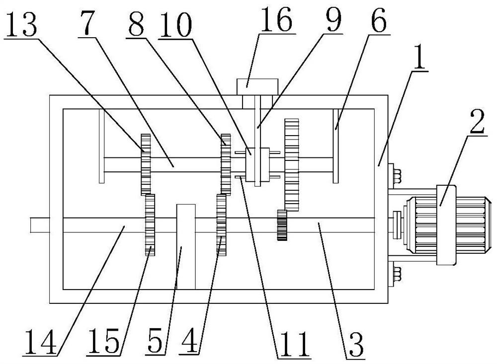
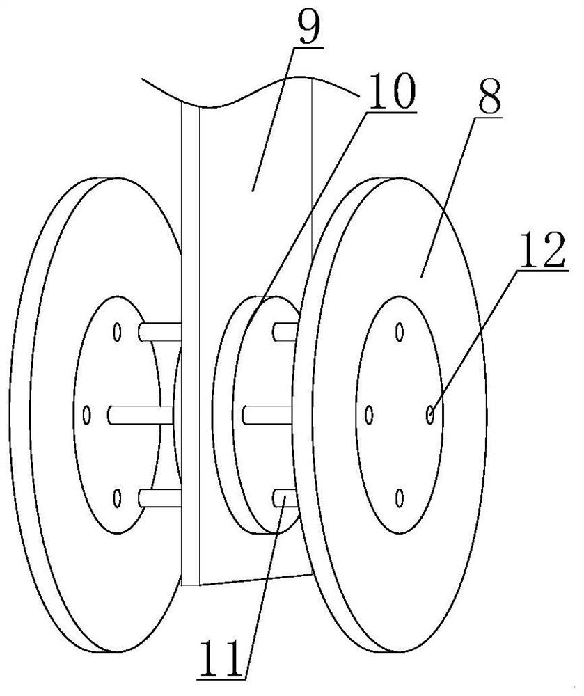
[0023] like figure 1 and image 3 As shown, this specific embodiment adopts the following technical solutions: an intelligent electric actuator with stable adjustment performance, comprising a casing 1, one end of the casing 1 is fixedly connected with a motor 2, and the output end of the motor 2 extends to the casing The inside of the body 1 is fixedly connected with a No. 1 transmission rod 3, the rod wall of the No. 1 transmission rod 3 is fixedly connected with a No. 1 gear set 4, the No. 1 gear set 4 is meshed with a No. 2 gear set 8, and the inner sleeve of the No. 2 gear set 8 is connected There is a No. 2 transmission rod 7, the two ends of the No. 2 transmission rod 7 are inserted with a No. 2 support plate 6, the No. 2 support plate 6 is fixedly connected with the inner wall of the housing 1, and the gears of the No. 2 gear set 8 are connected. Sleeve 10, the connecting sleeve 10 is fixedly connected with the No. 2 transmission rod 7, both ends of the connecting sle...

Embodiment 2

[0029] like Figure 2-5 As shown, this specific embodiment adopts the following technical solutions:

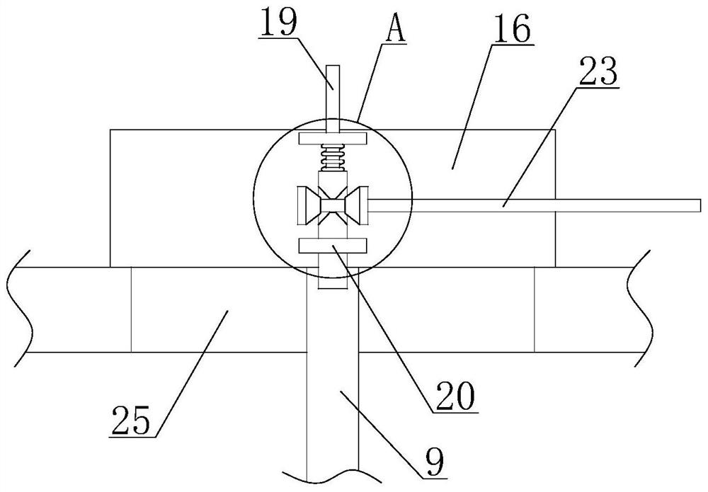
[0030] The top of the transmission block 16 close to the limit rod 21 is fixedly connected with a limit plate 17 , the middle of the limit plate 17 is inserted into the limit rod 19 , and the bottom of the limit rod 19 is fixed with the limit rod 21 The transmission block 16 is located below the No. 1 limit plate 17 and is fixedly connected with the No. 2 limit board 20. The limit rod 21 is inserted into the No. 2 limit board 20, and the top of the limit rod 21 is connected to the No. 1 limit board. A spring 18 is fixedly connected between 17 .

[0031] The upper end of the limit rod 21 is drilled with a No. 1 through hole 22 , a transmission rod 23 is inserted into the inside of the No. 1 through hole 22 , and a trapezoidal limit block 24 is fixedly connected to both sides of the transmission rod 23 located in the No. 1 through hole 22 . , both ends of the No. 1 through ho...


PUM


Abstract

An intelligent electric execution device with stable adjustment performance comprises a shell, one end of the shell is fixedly connected with a motor, the output end of the motor extends into the shell to be fixedly connected with a first transmission rod, the rod wall of the first transmission rod is fixedly connected with a first gear set, and the first gear set is in meshed connection with a second gear set; a second transmission rod is sleeved with the second gear set, the second gear set and the third gear set are connected through a connecting sleeve and the second transmission rod, a first inserting rod of the connecting sleeve can be inserted into an inserting hole of the second gear set according to needs, and one gear in the second gear set is connected with the second transmission rod. The transmission speed of the second gear set is changed, and adjustment can be conducted between rapid closing and slow closing; when the transmission rod is pulled, the trapezoidal limiting block on the transmission rod abuts against the first through hole, the inclined face is jacked up, the limiting rod is lifted, the transmission block can be moved, and therefore the purpose of adjusting the transmission gear in the second gear set is achieved.

Description

technical field [0001] The invention belongs to the technical field of electrical equipment, in particular to an intelligent electric actuator with stable adjustment performance. Background technique [0002] An electric actuator is a driving device that can provide linear or rotary motion. It uses a certain driving energy and works under the action of a certain control signal. The device converts it into a driving effect, which is widely used in electric valves and other fields. [0003] In the prior art, during the use of traditional electric actuators, the teeth of the internal reduction gear cannot be adjusted. After the production of electric actuators of the same type is completed, it cannot be adjusted. When the valves of some dangerous gases are operating. , If the rotation speed is too slow, it is difficult to quickly close the valve, leakage is likely to occur, and if it is in a fast-closing gear for a long time, it is easy to accelerate the damage of the valve. ...

Claims


Application Information

Patent Timeline
IPC IPC(8): F16K31/04F16K31/53H02K7/116
CPCF16K31/047F16K31/53H02K7/116
Inventor 邬学明邬学双
Owner 塞克赛斯流体设备(南京)有限公司
Why Eureka
Try Eureka