
Color gradation mapping method for maintaining image gradient direction

A color scale mapping and image gradient technology, which is applied in the field of image processing, can solve the problems of poor image visual effect, LDR image details, and non-protruding texture, and achieve the effect of prominent texture, high image definition, and good visual effect

Active Publication Date: 2022-08-05
HARBIN UNIV OF SCI & TECH
View PDF12 Cites 0 Cited by
  • Summary
  • Abstract
  • Description
  • Claims
  • Application Information

AI Technical Summary

Problems solved by technology

[0003] The purpose of the present invention is to solve the problem that the details and texture of the LDR image reconstructed by the traditional color scale mapping algorithm are not prominent, and the visual effect of the image is not good, and a kind of color scale mapping method that maintains the gradient direction of the image is proposed.

Method used


Image

  • Color gradation mapping method for maintaining image gradient direction
  • Color gradation mapping method for maintaining image gradient direction
  • Color gradation mapping method for maintaining image gradient direction

Examples


specific Embodiment approach 1

[0075] Specific implementation method I. A color grading method that keeps the gradient direction of the image gradient described in this method, which specifically includes the following steps:

[0076] Step 1: Select the diagonal pixels of HDR images;

[0077] Step 2: The collection of the diagonal pixel selected in the step 1 is used as a collection C, and each pixels in the collection C are maximized to obtain the brightness after the color graphics corresponding to each pixel;

[0078] Step 3: After the color grade mapping obtained in step 2 is used as the brightness of the corresponding pixels in the reconstruction LDR image, the collection of pixel composition that is not selected by the HDR image as one selected by the step of the HDR image is used as a collection E. According to the pixels in the collection E, The brightness value and color graphics in HDR images calculate the brightness of the pixel in the collection E in the reconstruction of the LDR image to obtain the...

specific Embodiment approach 2

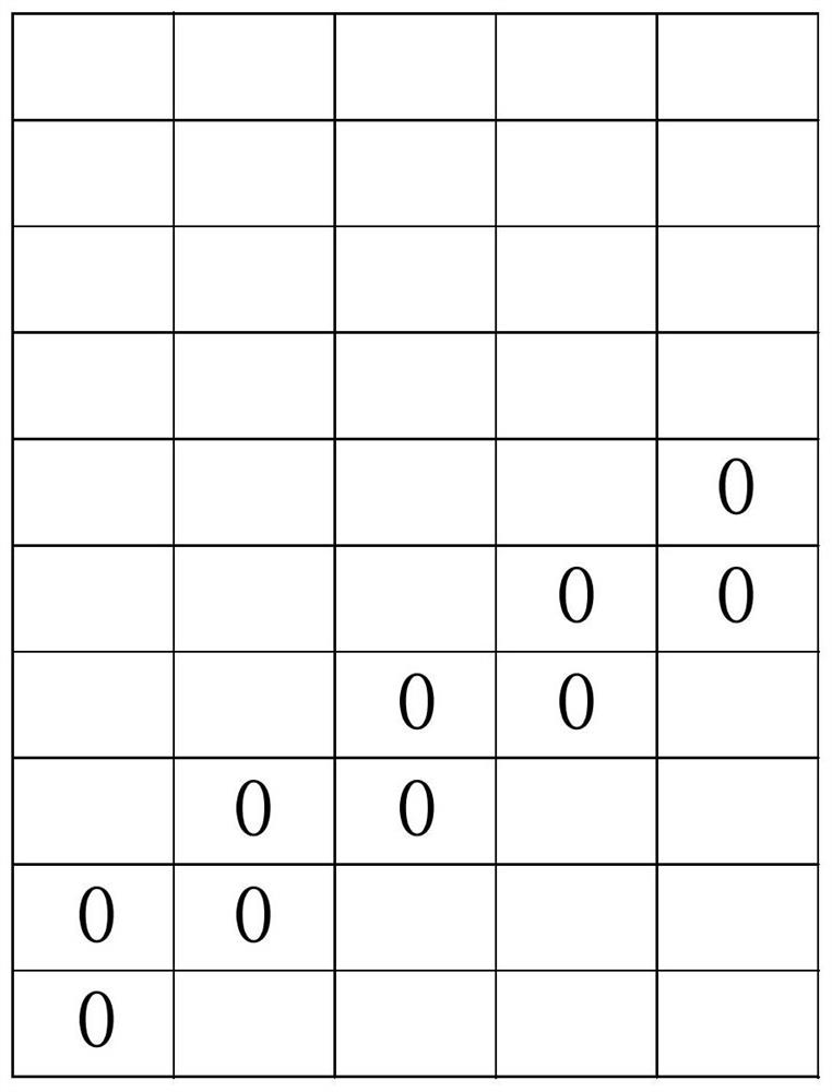
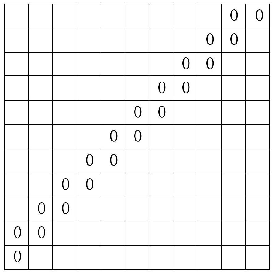
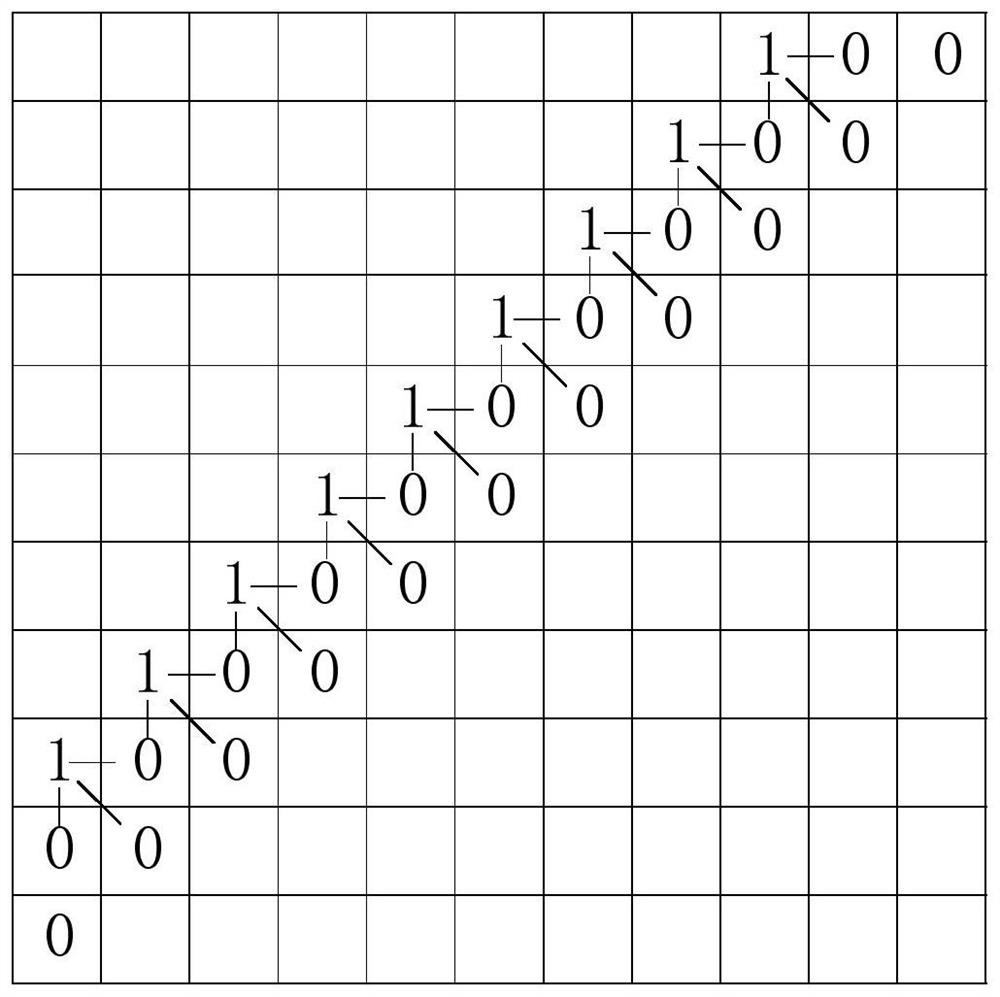
[0079] Specific implementation method 2: Combination figure 1 Explain this implementation method. The difference between this implementation method is different from the specific implementation method. In the step 1 of the step 1, the diagonal pixels of HDR images are selected. The pixels selected include two parts;

[0080] Among them, the choice of pixels is:

[0081] Step 1, select the left left corner of the HDR image as the starting pixel, and use the starting pixel as the current pixel;

[0082] Step 1 Two: Select the current pixel (when this step is executed for the first time, the current pixel is the starting pixel in step one. From the second execution of this step, the current pixel is determined by step 1st in the previous iteration process. The upper right of the current pixel) that is adjacent to the current pixel;

[0083] Step 1 and three, then select the pixels in step 1 and two as the current pixel;

[0084] Step 1, four, repeat steps, 1, two to one -to -three, u...

specific Embodiment approach 3

[0093] Specific implementation method three: The one or two of this implementation method is different from the specific implementation method. The specific process of the second step 2 is:

[0094] For any pixels in the collection C, the coordinate point of the pixel in the HDR image is represented by (m, n), (m, n) to represent the plane position where the pixel is located, and the brightness value of the pixel in the HDR image indicates the value. For L (m, n), the brightness I (m, n) corresponding to the color order of the pixel is:

[0095]

[0096] Among them, Max (C) and Min (C) represent the maximum brightness and minimum brightness of the pixels in the set C in HDR images, D min Represents the minimum brightness of the display, D max It represents the maximum brightness of the display.

[0097] Other steps and parameters are the same as specific embodiments.


PUM


Abstract

The invention discloses a color gradation mapping method for maintaining an image gradient direction, and belongs to the technical field of image processing. According to the method, the problems that the details and textures of the LDR image reconstructed by adopting a traditional color gradation mapping algorithm are not prominent, and the visual effect of the image is poor are solved. The method comprises the following steps: firstly, selecting diagonal pixels of an HDR image; secondly, performing color gradation mapping on diagonal pixel brightness; thirdly, deriving a brightness calculation method capable of keeping a gradient direction by using a Roberts operator; secondly, according to the brightness of the pixel of the diagonal line and a brightness calculation method for keeping the gradient direction, the brightness of all the pixels above the left side of the diagonal line is obtained through recursion; and finally, according to the brightness of the pixel of the diagonal and a brightness calculation method for keeping the gradient direction, carrying out recursion to obtain the brightness of all the pixels at the right lower part of the diagonal. Local details and textures of the LDR image reconstructed through the method are prominent, the image definition is high, and the overall visual effect of the image is good. The method can be applied to the technical field of image processing.

Description

Technical field [0001] The invention is a field of image processing technology, which involves a color grading method that keeps the gradient direction of the image. Background technique [0002] Because the dynamic range of conventional displays is far less than that of high dynamic range (HDR) images that are integrated through multiple exposure image synthesis methods, the color order mapping algorithm with dynamic range compression function is increasingly valued by the academic community. The main disadvantages of traditional color graphics algorithms are the details and textures of the low -dynamic range (LDR) images after reconstruction, and the image visual effects are not good. Invention content [0003] The purpose of the present invention is to solve the details and textures of the LDR image reconstructed by the traditional color grading algorithm. [0004] The technical solution taken by the present invention to solve the above technical issues is: [0005] A color g...

Claims


Application Information

Patent Timeline
IPC IPC(8): G06T5/00
CPCG06T5/90
Inventor 赵蓝飞李士俊李国庆刘发强
Owner HARBIN UNIV OF SCI & TECH
Learn More