
Slip-frequency-free continuously variable transmission

A continuously variable transmission and slip technology, which is applied in transmissions, elements with teeth, friction transmissions, etc., can solve the problems of narrow working temperature range of magnetorheological fluid, heat generation in the working area, irreversible thickening, etc. Achieve the effect of realizing basically no slip power transmission, reducing slip power, and solving heat generation problems

Pending Publication Date: 2022-08-09
CHINA UNIV OF MINING & TECH +1
View PDF1 Cites 0 Cited by
  • Summary
  • Abstract
  • Description
  • Claims
  • Application Information

AI Technical Summary

Problems solved by technology

[0003] For example, when the traditional dual magneto-rheological fluid governor with the authorized publication number CN101793312A performs speed regulation, slip heat generation is inevitable, but due to the narrow operating temperature range of the magnetorheological fluid (usually -40°C~130°C) , it is very easy to overheat during operation, resulting in the reduction of its mechanical properties and irreversible thickening, or even failure, which seriously restricts the practical application and rapid promotion of magnetorheological fluid governors
At present, air cooling or water cooling is mainly used for heat dissipation, and the effect is difficult to meet the actual use needs, and it cannot fundamentally solve the problem of heat generation in the working area during the transmission process

Method used


Image

  • Slip-frequency-free continuously variable transmission
  • Slip-frequency-free continuously variable transmission
  • Slip-frequency-free continuously variable transmission

Examples


Embodiment approach

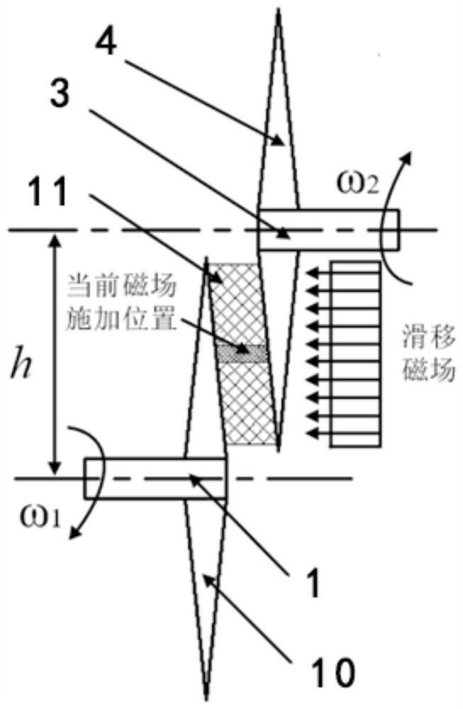
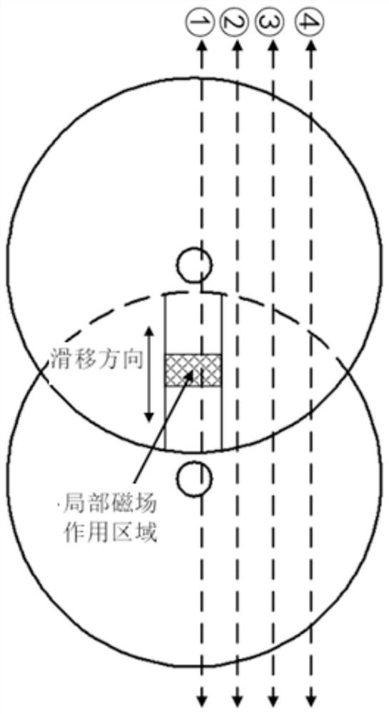
[0028] Further, the magnetic poles are connected with a screw-type linear push mechanism for driving the magnetic poles to move. As an embodiment of the present invention, the linear push mechanism 9 is an electric drive screw mechanism and is fixed on the housing 2 by bolts, which can be pushed to different positions on both sides and form a sliding magnetic field on the surface of the cone to solidify Magnetorheological fluids at different positions in the working gap.

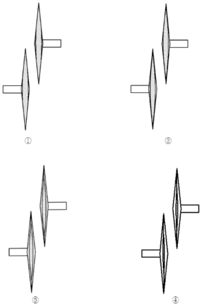
[0029] Further, the cross-sections of the disk edges of the driving disk and the driven disk are both trapezoidal, and the overall safety is improved after removing the top.


PUM


Abstract

The invention provides a slip-frequency-free continuously variable transmission. The slip-frequency-free continuously variable transmission comprises a shell, a driving shaft, a driven shaft, a conical-disc-shaped driving disc and a conical-disc-shaped driven disc. The driving shaft and the driven shaft are axially and fixedly installed at the center positions of the driving disc and the driven disc correspondingly. The driving disc and the driven disc are staggered in parallel by at least the radius, and a working gap exists between the driving disc and the driven disc. A shell is arranged to be buckled outside the driving disc and the driven disc, and the driving shaft and the driven shaft are installed on the shell through bearings. Magnetorheological fluid is arranged in the shell, magnetic poles capable of moving in the radial direction are arranged on the two sides of the staggered overlapping portion of the driving disc and the driven disc, and the magnetic poles are connected with a fixedly-arranged magnet exciting coil. The driving shaft and the driven shaft are in a non-coaxial transmission mode, and the problem of heat generation in the magnetorheological fluid stepless transmission process is solved. The driving disc and the driven disc are of a conical disc structure, the magnetic poles can slide to adjust the solidification position of the magnetorheological fluid in the working gap, the transmission ratio between the driving part and the driven part is continuously adjusted, and precise regulation and control of the stepless transmission speed of the magnetorheological fluid are achieved.

Description

technical field [0001] The invention relates to the field of magnetorheological variable speed regulation, in particular to a slipless stepless transmission. Background technique [0002] The traditional liquid viscous transmission uses the viscosity of the liquid or the shearing action of the oil film to transmit power. The working fluids usually used are Newtonian fluids such as lubricating oil, silicone oil and hydraulic transmission oil. Generally, the method of adjusting the thickness of the oil film and the shear area of ​​the oil film is used. to adjust the speed. In the past ten years, the application of magnetorheological fluid has developed rapidly, and the engineering application performance of magnetorheological effect has been further improved, so that it can be well used in the field of transmission. Magnetorheological fluid is a kind of intelligent material with superior performance, which is mainly composed of ultra-fine metal soft magnetic particles (0.1 mi...

Claims


Application Information

Patent Timeline
Patent Type & Authority Applications(China)
IPC IPC(8): F16H15/01F16H61/664
CPCF16H15/01F16H61/664
Inventor 田祖织吴向凡谢方伟季锦杰唐宇洁黄咸康郭阳阳
Owner CHINA UNIV OF MINING & TECH
Learn More