
Frictional disk drive mechanism of multiple rollers

A technology of transmission mechanism and friction disc, which is applied in the direction of friction transmission device, transmission device, mechanical equipment, etc., can solve the problems of continuous adjustment of transmission ratio, unstable operation of transmission mechanism, unstable change of transmission ratio, etc., and achieve Ensure stability, simple structure and low cost

Inactive Publication Date: 2008-01-23
WUHAN UNIV OF TECH
View PDF2 Cites 0 Cited by
  • Summary
  • Abstract
  • Description
  • Claims
  • Application Information

AI Technical Summary

Problems solved by technology

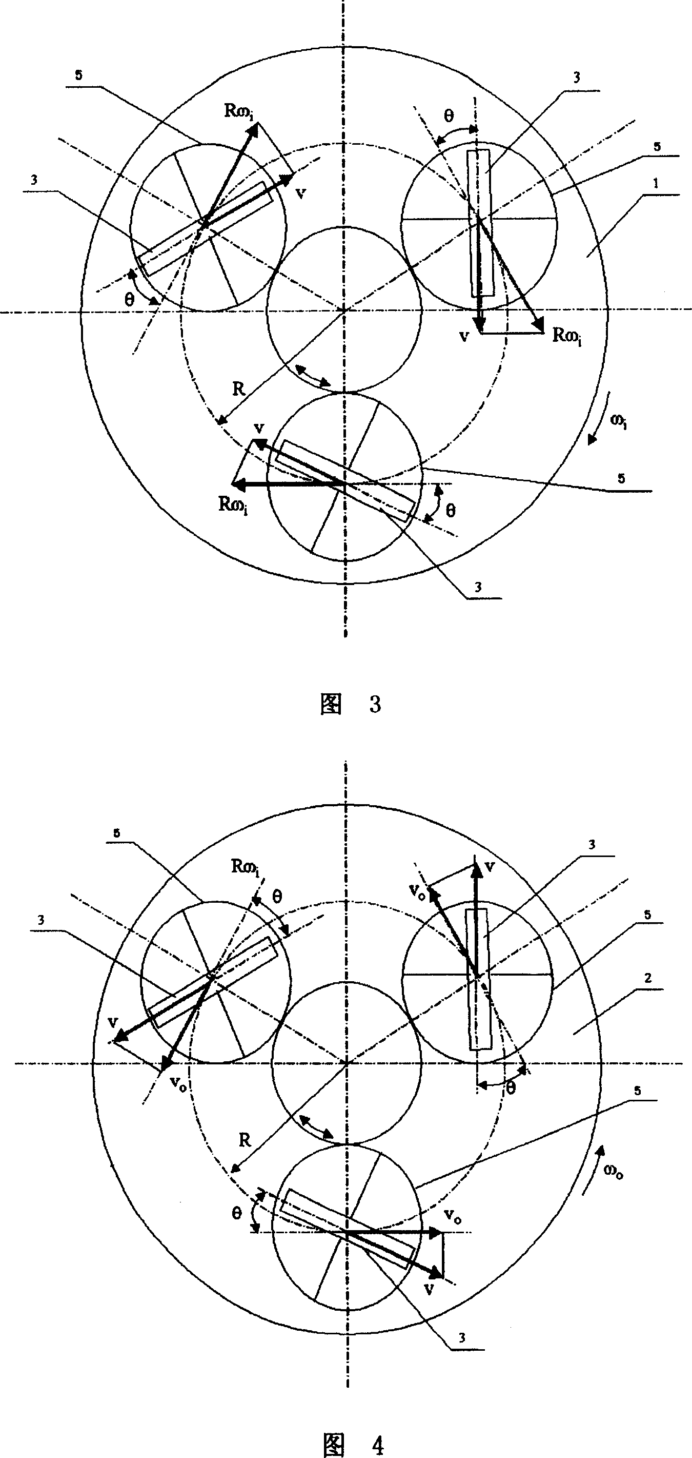
[0003] In the existing friction disc transmission mechanism shown in Figure 12, only one speed regulating roller 3 is set between the input disc 1 and the output disc 2, this is because: if more than two speed regulating rollers are set, when each speed regulating roller When the angular displacement of the speed roller rotation is different, it will cause an unstable change in the transmission ratio between the output disc and the input disc, and in fact the effect of continuously adjustable transmission ratio cannot be achieved.
[0004] However, there is only one speed-regulating roller between the input disc and the output disc, but it will cause the defect that the force of the input disc and the output disc is not uniform, so that the rotating shaft 8 of the input disc and the output disc is eccentrically stressed. Force, resulting in the instability of the entire transmission mechanism

Method used


Image

  • Frictional disk drive mechanism of multiple rollers
  • Frictional disk drive mechanism of multiple rollers
  • Frictional disk drive mechanism of multiple rollers

Examples


Embodiment Construction

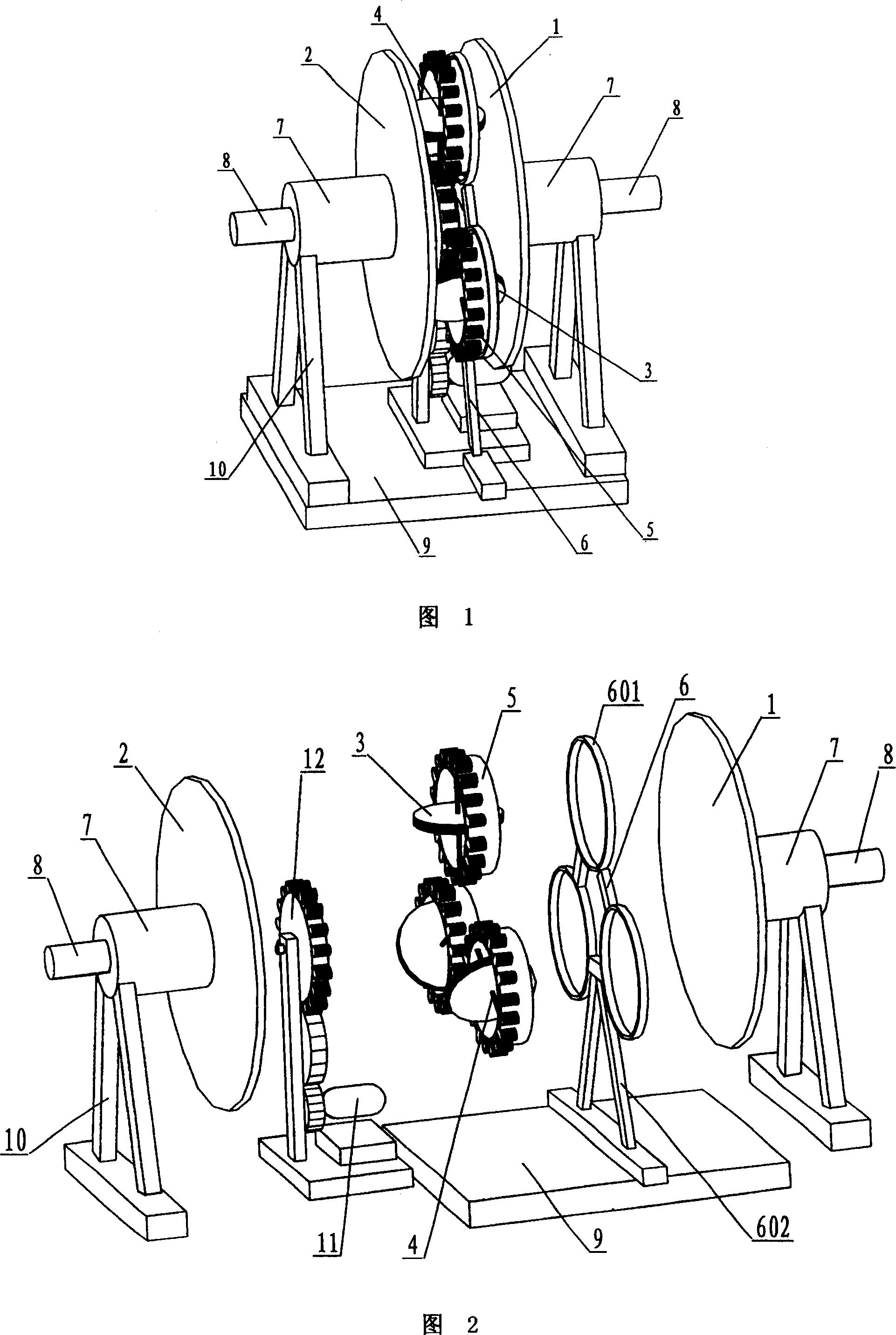
[0025] As shown in Figures 1 and 2, the transmission mechanism includes a base 9, an input disc 1, and an output disc 2, and the shafts 8 of the two discs 1 and 2 are respectively supported on the base 9 by a bracket 10 through a bearing 7 . Between the input disk 1 and the output disk 2, there are three speed regulating rollers 3 that can roll on the disk surfaces of the two disks 1 and 2, and each speed regulating roller 3 is evenly distributed on the disk surfaces between the two disks 1 and 2 Above, a steering linkage mechanism is arranged between the rotating shafts 4 of each speed regulating roller 3 .

[0026] As shown in Figures 1, 2 and 5, the transmission mechanism also includes three (same number as the speed regulating roller 3) circular rings 5, and a bracket 6 for supporting the circular rings 5 ​​on a plane. A speed regulating roller 3 is arranged in a circular ring 5 , and the two ends of the rotating shaft 4 of the speed regulating roller 3 are connected on t...


PUM


Abstract

A frictional disk driving mechanism with multiple contact rollers consists of input ring disk, output ring disk, two speed regulation contact rollers rolling on disk plane of two ring disks and being set between two said ring disks as each speed regulation contact roller being distributed on disk plane of two ring disks uniformly, and steering link gear between rotation shafts of each speed regulation contact roller.

Description

technical field [0001] The invention relates to a transmission mechanism, in particular to a friction disk transmission mechanism based on roller friction transmission. Background technique [0002] The existing friction disc transmission mechanism based on roller friction transmission (as shown in Figure 12), it comprises input disc 1, output disc 2, is provided with between input disc 1 and output disc 2 and can move between the two discs. The speed regulating roller 3 rolling on the disk surface of 1 and 2. Its working principle is: input the rotation ω of disc 1 i , drives the speed regulating roller 3 between the input disc 1 and the output disc 2 to roll, and the rolling speed regulating roller 3 makes the output disc 2 move at ω o turn. At this time, the transmission ratio relationship between the output disc 2 and the input disc 1 depends on the configuration of the speed regulating roller 3 relative to the input disc 1 and the output disc 2, that is to say, as lo...

Claims


Application Information

Patent Timeline
Patent Type & Authority Patents(China)
IPC IPC(8): F16H15/08F16H37/14
Inventor 谭跃刚曾盛琦
Owner WUHAN UNIV OF TECH
Learn More