Industrial vehicle with power steering apparatus and steering wheel angle correction device

A technology of industrial vehicles and steering equipment, applied in the direction of motor vehicles, automatic steering control components, lifting devices, etc.

Inactive Publication Date: 2004-11-03
TOYOTA IND CORP
View PDF2 Cites 0 Cited by
  • Summary
  • Abstract
  • Description
  • Claims
  • Application Information

AI Technical Summary

Problems solved by technology

Therefore, when the car is turning, the steering wheel angle correction will cause the wheels to be oversteered

Method used


Image

  • Industrial vehicle with power steering apparatus and steering wheel angle correction device
  • Industrial vehicle with power steering apparatus and steering wheel angle correction device
  • Industrial vehicle with power steering apparatus and steering wheel angle correction device

Examples


Embodiment Construction

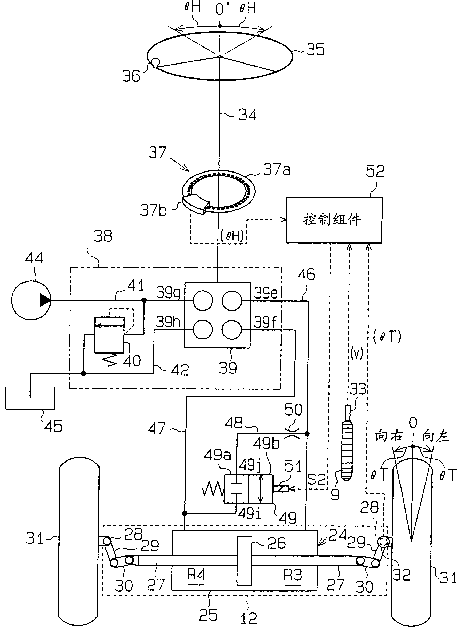
[0048] Combining the embodiment of a hydraulic steering device of the present invention Figure 1 to Figure 10 The introduction is as follows. This power steering equipment is used in forklifts or other industrial vehicles.

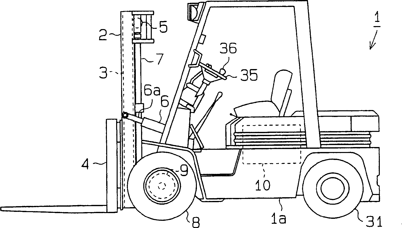
[0049] displayed on figure 2Forklift 1 in has driven front wheels and controlled steering rear wheels. The forklift 1 also has a body frame 1a. A pair of outer masts 2 are supported on the front of the vehicle body frame 1a in a tiltable manner. A pair of inner jibs 3 is arranged between the outer jibs 2 and a fork 4 is mounted on each inner jib 3 . The fork 4 is lifted and lowered in one piece along the outer mast 2 together with the cooperating inner mast 3 . A sprocket 5 is placed on top of each inner mast 3 . The top of each external jib is connected to the corresponding fork 4 via a chain (not shown), and the chain is connected to the corresponding sprocket 5 in turn. A pair of tilting cylinders 6 are arranged in front of the vehicle body fra...


PUM


Abstract

An industrial vehicle has rear wheels (119) steered by a hydraulic power steering apparatus in accordance with a rotation of a steering wheel (102). The vehicle includes an electromagnetic switching valve (122) that corrects discrepancies between an angular position of the steering wheel (102) and a wheel angle of the rear wheels (119) by racing the steering wheel (102) when the discrepancy exceeds a predetermined value. The vehicle further includes a central processing unit (141) that suppresses the operation of the switching valve (122) under certain conditions.

Description

technical field [0001] The present invention relates to a device for use in conjunction with industrial vehicles such as forklifts, which corrects for deviations between the steering wheel angle and the motor steered wheel angle. Background technique [0002] Typical motorized steering equipment is fully hydraulic, with a steering control cylinder and an oil pump. The oil pump sends oil to the steering control cylinder to aid in steering. The amount of oil sent to the cylinder is determined by the amount of rotation of the steering wheel. [0003] In industrial vehicles such as forklifts, the steering wheel is equipped with a round handle that allows the driver to control the vehicle with one hand while lifting loads with the other. The driver judges the wheel angle of the wheel by referring to the position of the knob. But when the efficiency of the control assembly (represented by dividing the actual oil discharge from the steering assembly by the theoretical oil discha...

Claims


Application Information

Patent Timeline
IPC IPC(8): B62D5/06B62D5/09B62D6/00B62D15/02
CPCB66F9/07568B62D15/02B62D5/09B62D6/00B62D5/06B60W10/20B60W2300/12B60W2510/20B62D6/002
Inventor 石川和男
Owner TOYOTA IND CORP
Why Eureka
Try Eureka