
Ink pressure controller for ink-jet head

A technology of pressure control and inkjet head, which is applied in printing and other directions, and can solve the problems of increasing the difficulty of manufacturing and assembly

Inactive Publication Date: 2004-11-17
IND TECH RES INST
View PDF1 Cites 0 Cited by
  • Summary
  • Abstract
  • Description
  • Claims
  • Application Information

AI Technical Summary

Problems solved by technology

[0011] However, since the stuffing element in the through hole is fixed and cannot move, in order to achieve the negative pressure value of the ink housing required for air bubbles to enter, it is necessary to accurately control and calculate the gap between the stuffing element and the through hole, so that Increased difficulty in manufacturing and assembly

Method used


Image

  • Ink pressure controller for ink-jet head
  • Ink pressure controller for ink-jet head
  • Ink pressure controller for ink-jet head

Examples


Embodiment 1

[0033] see Figure 1A , 1B shown.

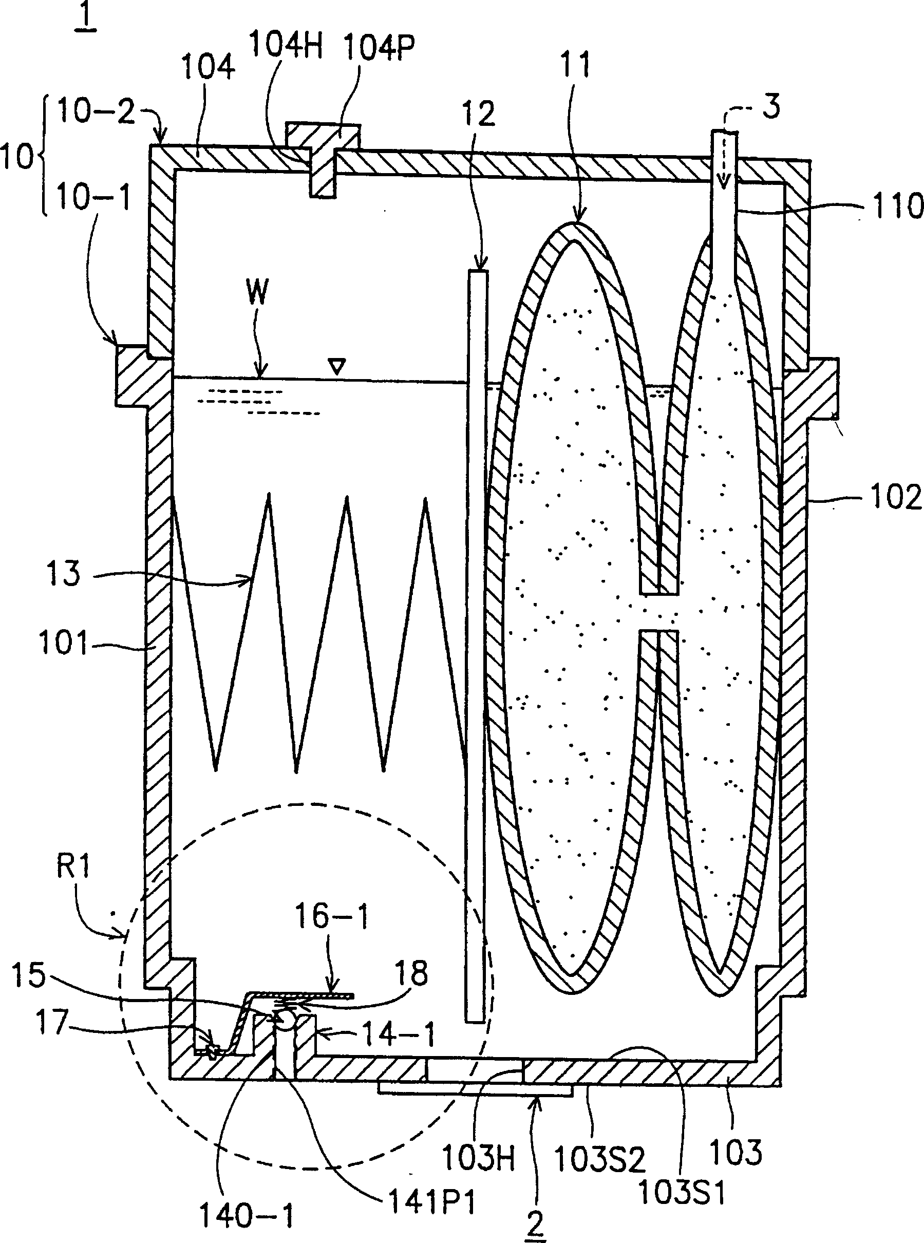
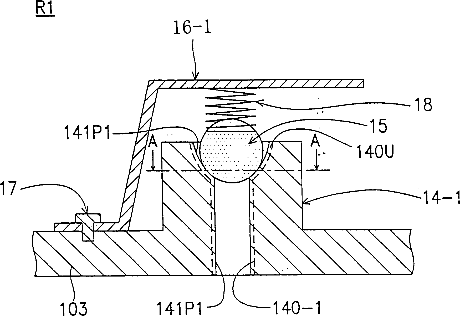
[0034] Figure 1A A schematic view showing an ink cartridge 1 according to a first embodiment of the present invention, Figure 1B According to Figure 1A An enlarged view of the regulator R1.

[0035] Such as Figure 1A As shown, the ink cartridge 1 includes a container 10, an air chamber 11, a plate 12, a spring 13 and a print head 2, wherein the container 10 is used to hold ink W, and the ink cartridge 1 can provide a printing device (not shown) Shown) the required ink W, and there is a negative pressure in the gas inside the container 10. The container 10 has a through hole 140 - 1 (at the bottom of the container 10 ), and the through hole 140 - 1 is an air hole of the container 10 .

[0036] The ink pressure control device of the inkjet head of the present invention is arranged on the ink cartridge 1, and the ink pressure control device of the inkjet head mainly includes a base 14-1 and a regulating device R1 (the dotted line positio...

Embodiment 2

[0059] see Figure 3A , 3B .

[0060] Figure 3A A schematic view showing an ink cartridge 1' according to a second embodiment of the present invention, Figure 3B According to Figure 3A Enlarged view of the regulator R2.

[0061] Such as Figure 3A , 3B As shown, the difference from the first embodiment is that the ink cartridge 1' is replaced by an elastic element 16' to replace the plate 16-1, and the elastic element 16' presses the stuffing element 15 into contact with several protrusions Above 141P2.

[0062] The elastic element 16' is composed of a reed, and the elastic element 16' is bonded and fixed on the bottom plate 103 by means of a bonding material 17 or by thermal fusion. The elastic element 16' can be divided into a first section 16'-1 and a second section 16'-2, wherein the first section 16'-1 is used to abut the stuffing element 15 against several protrusions in the accommodation chamber 140U On the portion 141P, the second section 16 ′ - 2 abuts aga...


PUM


Abstract

An ink pressure controller of ink-jet nozzle has a base and a regulator. Said base has a through hole with several recesses for communicating the negative pressure in ink box with atmosphere. Said regulator has a filling element and an elastic element. The gap between filling element and through hole can be regulated by the elastic element. When negative pressure in casing is gradually raised, the atmosphere pressure makes air come in the casing through said gap to generate air bubbles to prevent negative overpressure, stabilizing the ink supply.

Description

technical field [0001] The invention relates to an ink pressure control device for an inkjet head, in particular to an ink pressure control device for an inkjet head that avoids excessive negative pressure inside the ink casing. Background technique [0002] In general inkjet printing, in the method of controlling the output of ink from the ink shell to the printing paper, the drop-on-demand method (Drop-On-Demand) is a commonly used method, and a typical printing device using the drop-on-demand method is Most of them use thermal bubble type or piezoelectric electric wave type. [0003] The thermal bubble print head includes a thin film resistor, which can vaporize a small amount of ink droplets instantly after being heated. The rapid expansion of the ink droplets after evaporation allows a small amount of ink to pass through the nozzles of the print head and then printed on the paper. Although the print head of the drop-on-demand method can effectively obtain ink from the ...

Claims


Application Information

Patent Timeline
Patent Type & Authority Patents(China)
IPC IPC(8): B41J2/07B41J2/175
Inventor 谢树峥苏士豪许成伟陈锦泰侯怡仲王介文
Owner IND TECH RES INST
Learn More