
Printer

a printing machine and thermal printer technology, applied in printing, other printing apparatus, etc., can solve the problems of poor printing quality and affect the quality of printing paper on the printing paper sheet, and achieve the effect of avoiding instantaneous momentum and reducing the effect of printing quality

Active Publication Date: 2021-04-01
XIAMEN HANIN ELECTRONICS TECH CO LTD
View PDF0 Cites 0 Cited by
  • Summary
  • Abstract
  • Description
  • Claims
  • Application Information

AI Technical Summary

Benefits of technology

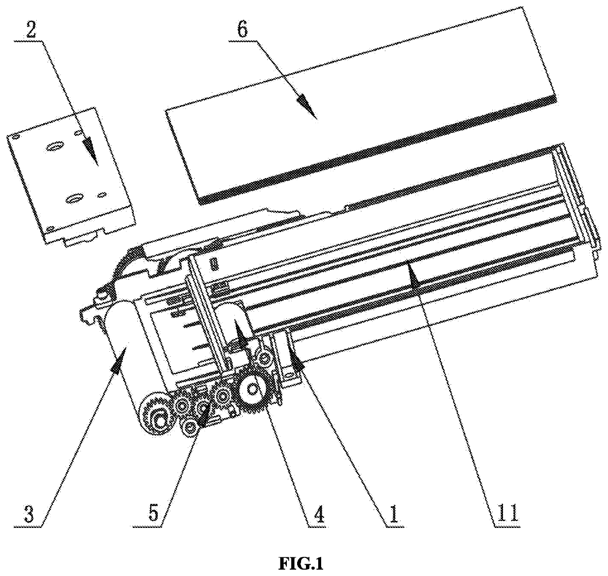
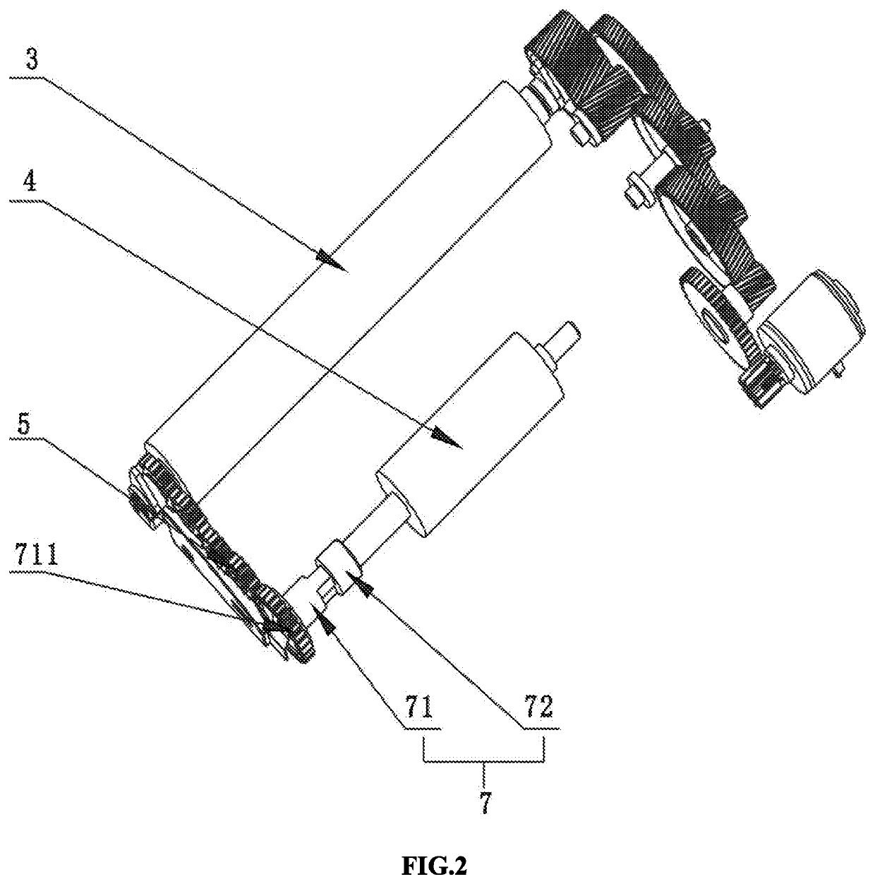
The present disclosure provides a thermal printer that can prevent the impact force generated by the remaining printing paper sheet that falls and is transmitted to the platen roller, which affects the quality of printing on the paper sheet, and can provide smooth printing. The printer includes a base part, a gear set, a platen roller, a pickup roller, and a thermal head. A clutch mechanism is included to reduce the impact force transmitted to the platen roller. The arrangement of the driving member and the pickup roller mounting frame reduces the impact force transmitted to the platen roller. The linear velocity of the paper sheet transmitted at the platen roller is greater than the linear velocity of the paper sheet transmitted at the pickup roller to avoid shaking of the platen roller. This reduces the impact force transmitted to the platen roller and improves printing quality.

Problems solved by technology

The sloshing lead to a deflection of engagement between the platen roller and the thermal head and resulting in poor printing quality.
The impact force may be transmitted to the platen roller and affects the quality of printing on the printing paper sheet.

Method used


Image

  • Printer
  • Printer
  • Printer

Examples


second embodiment

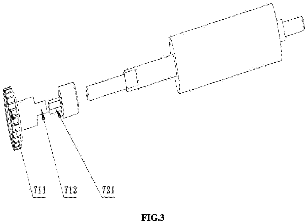
[0035]In the second embodiment, the clutch mechanism 7 may be arranged coaxially with the rotation shaft of the pickup roller 4, and the driven member 72 may be rotated along with the rotation shaft of the pickup roller 4. Preferably, the driven member 72 may be integrally formed with the rotation shaft of the pickup roller 4. The driving member 71 may be rotatably sleeved on the rotation shaft of the pickup roller 4. Others are similar to those arrangements in the first embodiment and are not repeated here.


PUM


Abstract

A thermal printer comprises a base part, a platen roller and a thermal head oppositely arranged, a pickup roller, and a gear set connecting the platen roller and the pickup roller. The base part is provided with a printing paper accommodating cavity and a pickup roller mounting frame, a plurality of printing paper sheets are disposed in the printing paper accommodating cavity, and a clutch mechanism is further provided. The clutch mechanism comprises a driving portion driven by the gear set and a driven portion for driving the pickup roller to rotate. The driving portion is disposed outside the pickup roller mounting frame, such that the impact force, which is generated by the remaining printing paper sheet that falls down when the printing paper sheet departs from the pickup roller and which is transmitted to the platen roller, can be reduced. The thermal printer is capable of providing smooth printing.

Description

CROSS-REFERENCE TO RELATED APPLICATIONS[0001]The present application claims the benefit under 35 U.S.C. § 119 of China Patent Application No. 201921667025.1, filed on Sep. 30, 2019, in the China National Intellectual Property Administration, the content of which is hereby incorporated by reference.FIELD OF THE INVENTION[0002]The present disclosure relates to the technical field of printers, more particularly to a thermal printer capable of providing smooth printing.BACKGROUND OF THE INVENTION[0003]The pickup roller installed on the printer can be driven by the platen roller via the gear set and rotated therewith. When the pickup roller is rotated, the lowermost one of the loaded printing paper sheets which are in contact with the pickup roller is fed frontward as the rotation of the pickup roller. The printing paper sheets can be fed due to the friction between the printing paper sheets and the circumferential surface of the pickup roller. And then the printing paper sheet is separa...

Claims


Application Information

Patent Timeline
IPC IPC(8): B41J11/04B41J11/51B41J11/44B41J2/33
CPCB41J11/04B41J2/33B41J11/44B41J11/51B41J13/103B41J2/32B41J11/24B41J2/315B41J23/02
Inventor LIU, ZHIPING
Owner XIAMEN HANIN ELECTRONICS TECH CO LTD
Learn More