
Eureka
For R&D, Eureka makes reading and utilizing patents & technical documents easy.
Eureka AIR
Designed for self-driven R&D workflows. Generate viable solutions, solve complex R&D challenges, empower your innovation with AI.

Eureka Materials
Designed for material experts only. Revolutionize your material R&D, from search, analyze, to developing new materials.

TechResearch
Generate reliable direction feasibility study reports for your R&D in just a few steps.

TechSeek
Discover and master advanced knowledge NOW. Basics, ideas, possibilities, all at once.

TechMind
As an expert in R&D Theories, TechMind can generates customized viable solutions instantly.

TechRisk
Analyze your overall solution with one click, know your potential R&D risks in advance.

TechMonitor
Get weekly tech updates, stay abreast of the latest tech innovations and key insights.
Hypersonic liquid jet generator
A liquid jet, supersonic technology, applied in the direction of liquid injection devices, injection devices, etc., can solve the problems of damage, waste, nozzle deformation, etc., and achieve the effect of convenient use and simple design
- Summary
- Abstract
- Description
- Claims
- Application Information
AI Technical Summary
Problems solved by technology
Method used
Image

Examples
Embodiment Construction
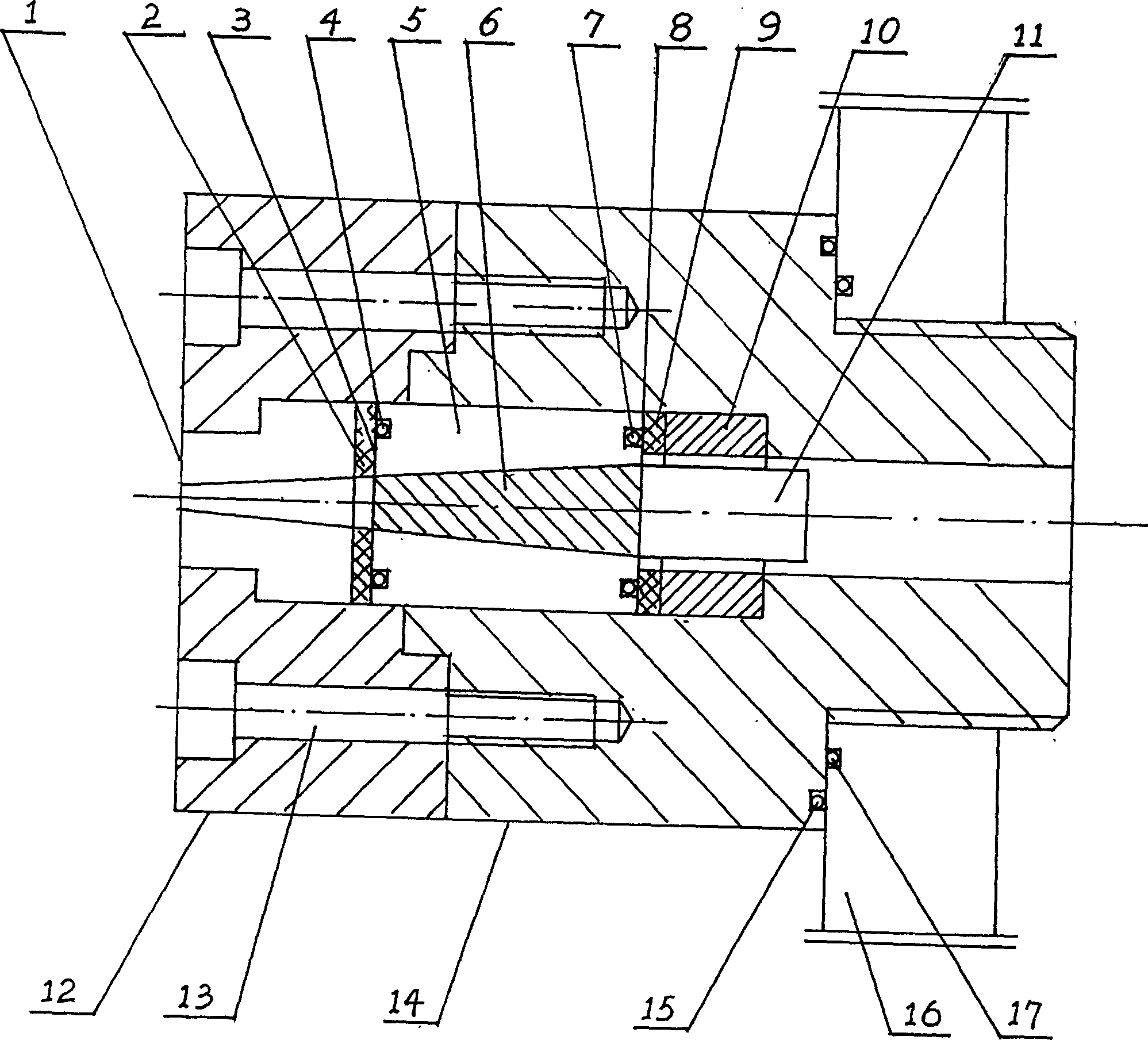
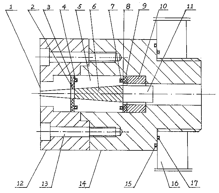
[0007] The hypersonic liquid jet generating device has an outer chamber 14, in which a free piston 11, an adjustment ring 10, a rubber gasket 9, a diaphragm 8, an O-ring 7, a liquid chamber 5, and an O-ring are sequentially arranged. 4. Diaphragm 3, rubber gasket 2, nozzle 1, there is an annular step outside the nozzle 1 and a matching top flange 12, the top flange 12 and the outer chamber 14 are fixed with hexagon socket head cap screws 13, and the outer chamber 14 is threaded It is fixed on the supporting flange 16, and the outer side of the rear end of the outer chamber 14 is provided with an external thread interface, which is connected with the inner thread of the supporting flange 16, and the contact surface between the outer chamber 14 and the supporting flange 16 is provided with an O-shaped seal Circles 15 and 17.
[0008] Said liquid chamber 5 is conical, and liquid 6 is arranged in the liquid chamber 5 .
[0009] The hypersonic liquid jet generating device has an i...
PUM
 Abstract
Description
Claims
Application Information
 - R&D Engineer
- R&D Manager
- IP Professional
- Industry Leading Data Capabilities
- Powerful AI technology
- Patent DNA Extraction
Browse by: Latest US Patents, China's latest patents, Technical Efficacy Thesaurus, Application Domain, Technology Topic, Popular Technical Reports.
© 2024 PatSnap. All rights reserved.Legal|Privacy policy|Modern Slavery Act Transparency Statement|Sitemap|About US| Contact US: help@patsnap.com