Mobile communication terminal including camera
A technology of mobile communication terminals and cameras, which is applied in communication between multiple stations, image communication, static cameras, etc., and can solve problems such as difficulty in providing images
- Summary
- Abstract
- Description
- Claims
- Application Information
AI Technical Summary
Problems solved by technology
Method used
Image
Examples
no. 1 example
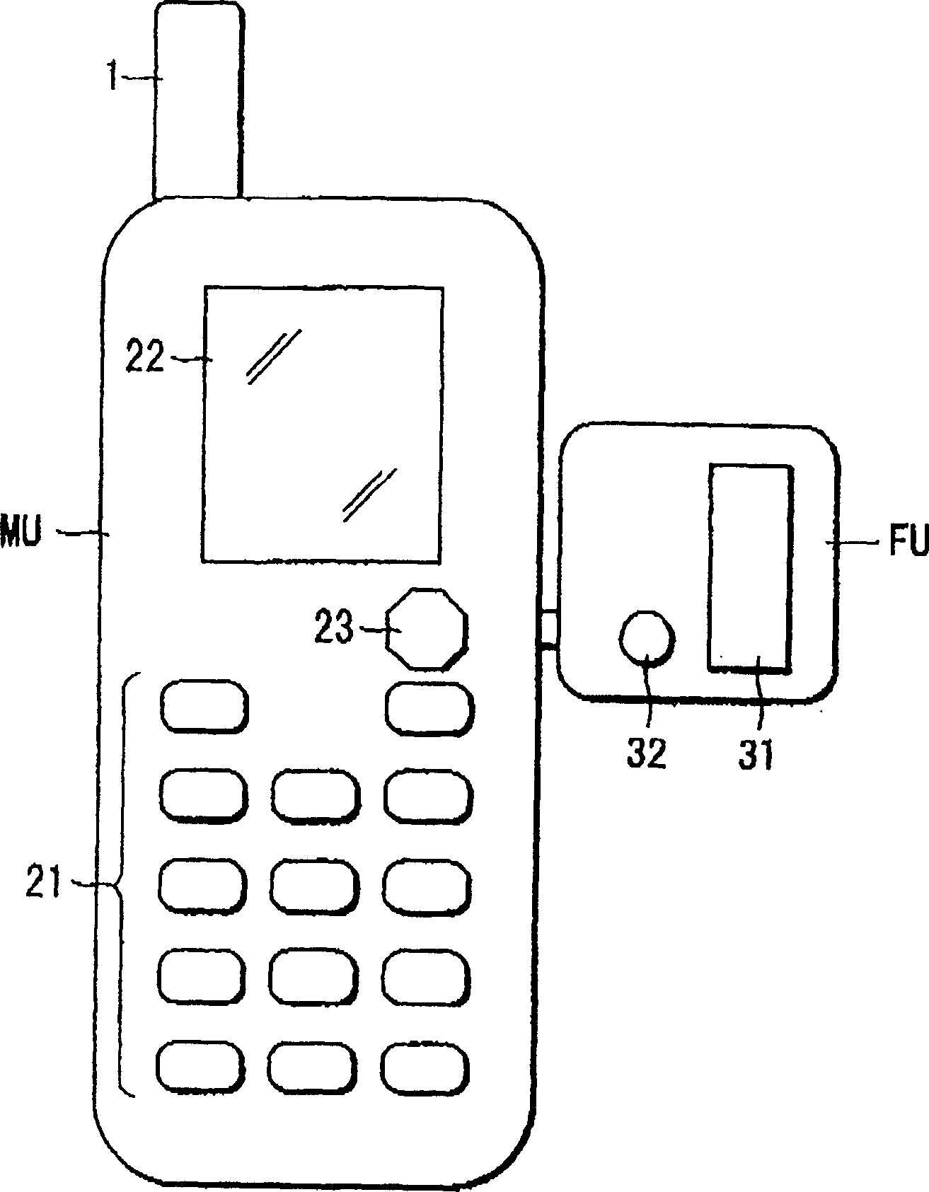
[0063] figure 1 Denotes a mobile communication terminal MU according to a first embodiment of the present invention. The terminal MU can also be used as a camera.
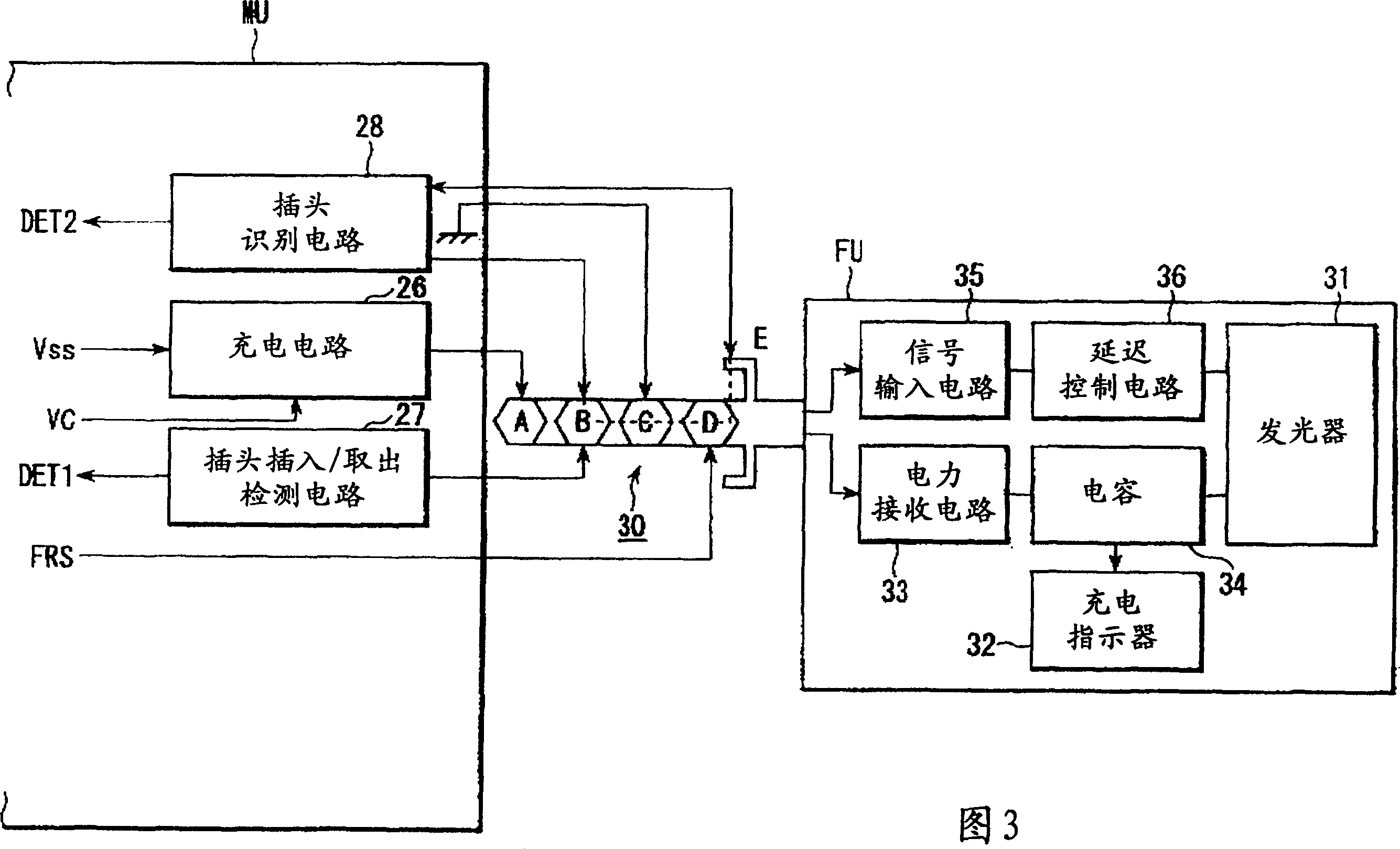
[0064] The terminal MU consists of an enclosure. The antenna 1 is mounted on the upper part of the housing. A keyboard input section 21, a display section 22, and a camera 23 are arranged on the front panel of the housing. In addition, a headphone jack is provided on one side of the case. The flash unit FU is connected to the headphone jack and can be removed from said jack. The flash unit FU has a light emitting part 31 and a charging indicator 32 . The light emitting unit 31 is disposed on the front of the flash unit FU. Charge indicator 32 comprises a neon tube.
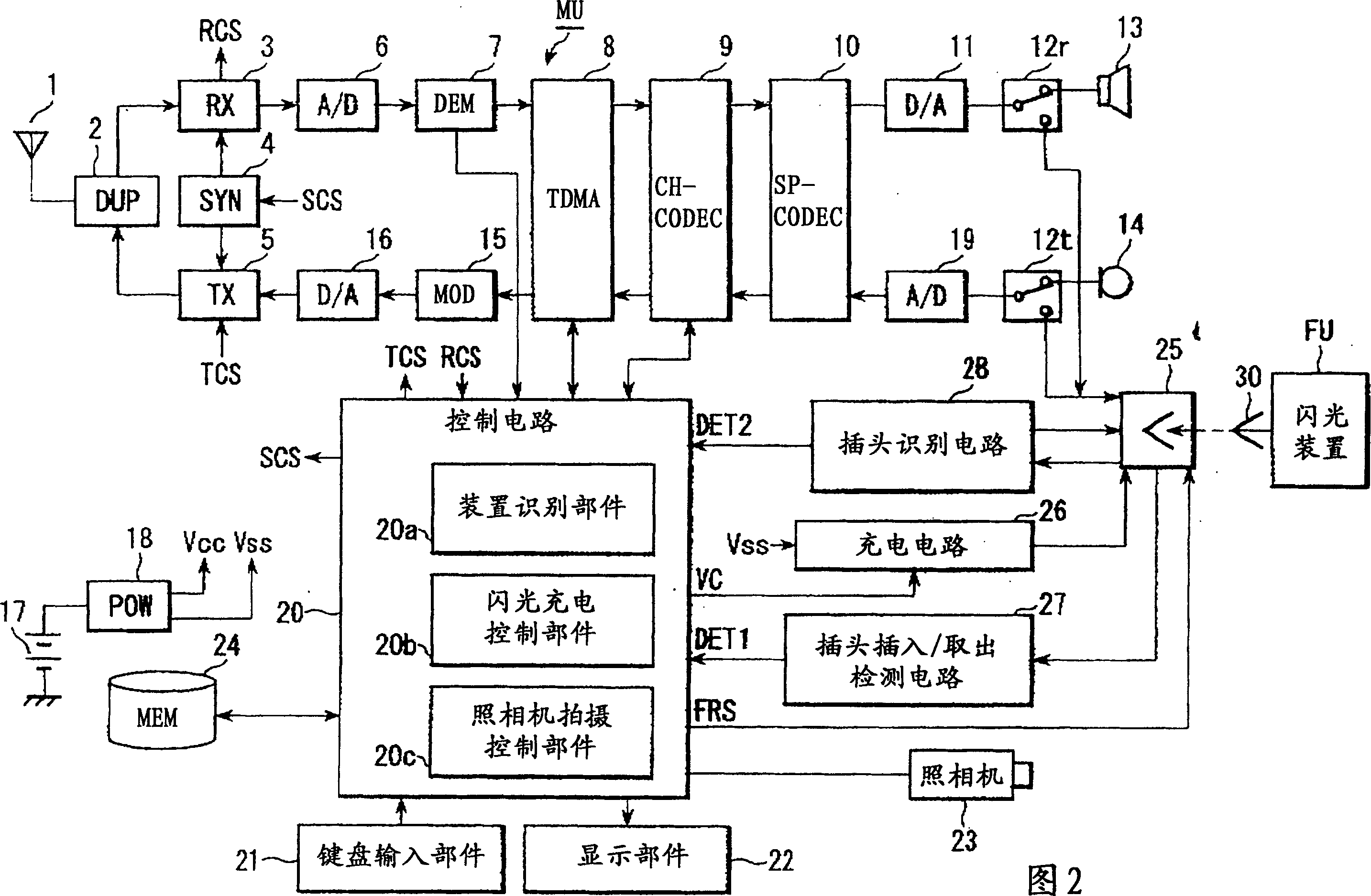
[0065]Fig. 2 shows the circuits contained in the mobile communication terminal MU.
[0066] As shown in FIG. 2, the antenna 1 receives a radio signal from a base station (not shown in the figure) through a radio channel. In terminal MU, receiv...
no. 2 example
[0128] A second embodiment of the mobile communication terminal according to the invention comprises a camera and a flash circuit. A high-intensity flash lamp such as a xenon lamp is used as the light emitting part of the second embodiment. The flash circuit includes a charging / discharging circuit that drives a high-intensity flash. In addition, timing control is performed to prevent charging of the charging / discharging circuit and radio communication from overlapping each other in time.
[0129] Figure 10 is a front view of a mobile communication terminal according to a second embodiment of the present invention.
[0130] Mobile communication terminals are foldable terminals. The terminal has a box-shaped upper body A and a box-shaped lower body B. Fuselages A and B are connected to each other by a hinge C. Hinge C enables the bodies A and B to rotate relative to each other. A liquid crystal display (LCD) 221 and a speaker (not shown in the figure) for receiving calls ...
no. 3 example
[0186] A third embodiment of a mobile communication terminal according to the present invention has a camera and a flash circuit both provided in the terminal housing. A solid-state light-emitting component such as a white light-emitting diode (white LED) is used as the light-emitting component. Thus, real-time light emission can be realized when a light-emitting driving signal is supplied from the control circuit to the light-emitting diode. Thus, the terminal can capture not only still images in flash mode but also moving images in continuous camera mode. In addition, the timing of light emission and radio transmission / reception operations is controlled so as to prevent them from overlapping each other.
[0187] Figure 15is a circuit block diagram of the mobile communication terminal according to the third embodiment. In terms of appearance, the mobile communication terminal and Figure 10 The mobile communication terminals shown in are basically the same.
[0188] Suc...
PUM
 Abstract
Description
Claims
Application Information
 - R&D
- Intellectual Property
- Life Sciences
- Materials
- Tech Scout
- Unparalleled Data Quality
- Higher Quality Content
- 60% Fewer Hallucinations
Browse by: Latest US Patents, China's latest patents, Technical Efficacy Thesaurus, Application Domain, Technology Topic, Popular Technical Reports.
© 2025 PatSnap. All rights reserved.Legal|Privacy policy|Modern Slavery Act Transparency Statement|Sitemap|About US| Contact US: help@patsnap.com


