
Cloth bonding apparatus

A cloth bonding and adhesive technology, applied in the field of cloth bonding devices, can solve the problems of unable to control the pressure, unable to reach sufficient gas pressure in the storage room, unable to press out the adhesive, etc.

Inactive Publication Date: 2012-09-26
BROTHER KOGYO KK
View PDF1 Cites 0 Cited by
  • Summary
  • Abstract
  • Description
  • Claims
  • Application Information

AI Technical Summary

Problems solved by technology

When the storage chamber is not sealed (for example, when the lid of the storage chamber is open), it is impossible to achieve sufficient gas pressure in the storage chamber
Therefore, this device cannot control the pressure in the storage chamber based on the measured gas pressure, and there is a problem that sometimes an appropriate amount of adhesive cannot be pressed out of the storage chamber.

Method used


Image

  • Cloth bonding apparatus
  • Cloth bonding apparatus
  • Cloth bonding apparatus

Examples


no. 1 approach

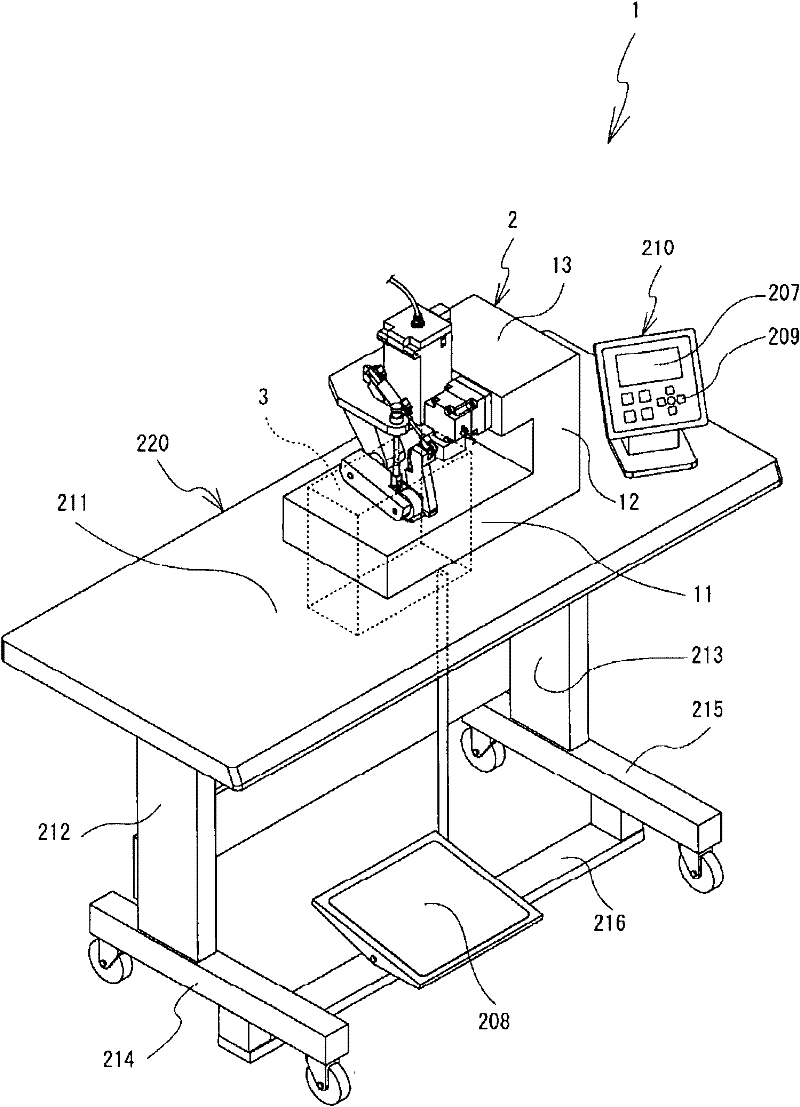
[0032] Next, a first embodiment of the cloth bonding apparatus 1 of the present invention will be described with reference to the drawings.

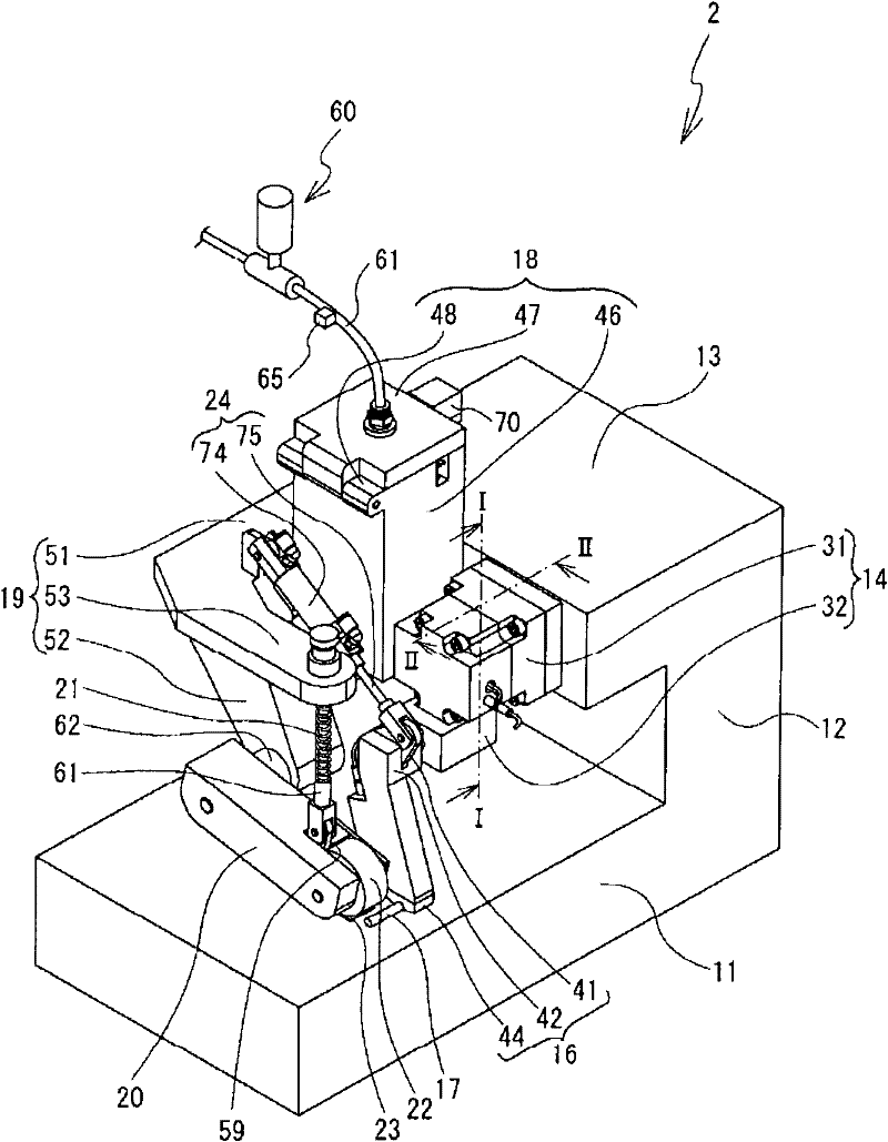
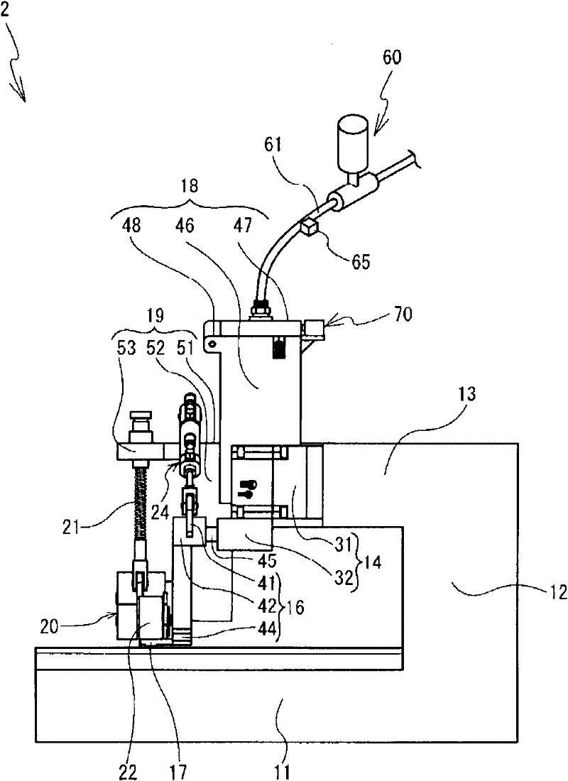
[0033] refer to Figure 1 to Figure 4 , the structure of the cloth bonding apparatus 1 will be described. Next, put image 3 The upper side, the lower side, the right side, the left side, the front side, and the back side of the bonding machine 2 are defined as the upper side, the lower side, the right side, the left side, the front side, and the back side of the bonding machine 2 respectively. Explained on the back side.

[0034] Such as figure 1 As shown, the cloth bonding apparatus 1 includes a bonding machine 2 and a use table 220 . The bonding machine 2 is fixed using a table 220 . The bonding machine 2 applies an adhesive between two layers of cloths arranged opposite to each other, and presses and feeds the cloths. The two layers of cloth are bonded by the above operation of the bonding machine 2 . The detailed structure of...

no. 2 approach

[0105] Next, a second embodiment will be described. The same symbols are assigned to the same structures as those in the first embodiment, and description thereof will be omitted.

[0106] refer to Figure 14 , the configuration of the cloth bonding apparatus 5 will be described. The cloth bonding device 5 includes a compressor 75 . The shape of the compressor 75 is substantially cylindrical with the vertical direction being the longitudinal direction. The compressor 75 is installed on the left side of the foot 212 of the table 220 . One end of the hose 61 is connected to the upper part of the compressor 75 . The other end of the hose 61 is connected to the cover 47 of the storage chamber 18 . The compressor 75 sends gas towards the storage chamber 18 through the hose 61 . The compressor 75 can supply gas pressure into the storage chamber 18 through the hose 61 . The CPU 201 can electrically control the operation of the compressor 75 .

[0107] The valve 60 is provided...


PUM


Abstract

A cloth bonding apparatus includes a valve. The valve controls a gas pressure to be supplied into a storage chamber. The storage chamber stores an adhesive therein. A CPU of the cloth bonding apparatus prohibits a cover portion of the storage chamber from being open (S11) and opens the valve (S13). The CPU passes the gas into the storage chamber via the valve and supplies a gas pressure into the storage chamber. The CPU obtains the gas pressure inside the storage chamber detected by a pressure sensor (S15), and when the obtained gas pressure is less than a predetermined value (S17: NO), closes the valve (S21). The CPU prohibits a gear pump from rotating and stops feeding cloths (S23). The cloth bonding apparatus can prevent that a sufficient gas pressure is not supplied into the storage chamber 18 and an appropriate amount of adhesive can not be discharged from the storage chamber.

Description

technical field [0001] The invention relates to a cloth bonding device. More specifically, the present invention relates to a cloth bonding apparatus including a storage chamber for storing an adhesive. Background technique [0002] Instead of using needles and stitches to sew cloth, the cloth bonding device uses adhesives to bond cloth to cloth. The cloth bonding device can eliminate seam unevenness that occurs on the cloth surface during sewing due to seams by bonding cloth to cloth with an adhesive. When using the cloth bonding device, the surface of the processed cloth is smooth. Clothes made of this cloth will not cause discomfort due to uneven seams when worn. Therefore, the cloth bonding device can produce clothes that do not feel uncomfortable when worn. [0003] The cloth bonding device discharges the liquid adhesive from the nozzle. The adhesive adheres to the cloth. The operator then overlaps other cloths on the cloth with the adhesive attached. The cloth b...

Claims


Application Information

Patent Timeline
Patent Type & Authority Patents(China)
IPC IPC(8): B29C65/52
CPCB29K2313/00B29C66/934B29C65/48B29C65/4815B29C66/729B29C66/1122B29C66/8161B29C66/8748B29C66/43B29C66/83413A41H43/04B29C66/9672B29C66/92B29C66/872B29C66/96B29C66/9674B29C66/93451B29C66/942B29C66/9221B29C65/524B29C66/845B29C66/431B29C66/8167B29C66/8221B29C66/876B29C66/932B29C66/961
Inventor 多田悟吉本直树大村义和梅田和俊岩越弘恭山浦宏贵盐谷哲司
Owner BROTHER KOGYO KK
Learn More