
An Improved Structure of a Steam Generator

A technology of steam generator and steam outlet, which is applied in the direction of cleaning carpets, floors, cleaning equipment, etc. It can solve the problems of not being able to supply steam to users, affecting normal use of users, and not having enough heating elements.

Inactive Publication Date: 2017-01-18
广东佳明电器有限公司
View PDF7 Cites 0 Cited by
  • Summary
  • Abstract
  • Description
  • Claims
  • Application Information

AI Technical Summary

Problems solved by technology

When this kind of steam generator needs to stop supplying steam, it just stops injecting water into the steam generator and stops supplying power to the columnar heating element. At this time, the columnar heating element still has relatively large heat energy. In this case, it is easy Because the heating element does not have enough heat energy supply, it is not enough to evaporate the water remaining in the shell, resulting in a water-steam mixture instead of steam supplied to the user, which will affect the normal use of the user (such as the water flowing out of the floor mop) It is water vapor instead of steam, and secondly, the supply of steam to users cannot be stopped immediately according to the control

Method used


Image

  • An Improved Structure of a Steam Generator

Examples


Embodiment Construction

[0017] Now in conjunction with accompanying drawing and embodiment the present invention is described in further detail:

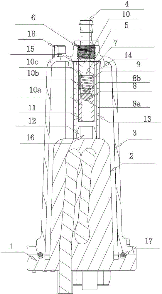
[0018] As shown in the figure, the present invention includes a columnar heating element 2 with a fixed base plate 1, a housing 3 that is set outside the columnar heating element 2 and fixed on the fixed base plate 1, and a sealing ring 17 is arranged between the housing 3 and the fixed base plate 1 The casing 3 is provided with a steam outlet 4 and a water injection port 18. The steam outlet 4 is located on the top of the casing 3. The special feature is that a valve 5 is connected under the steam outlet 4, and the valve 5 is threaded to seal the thread on the top of the casing 3. In the hole 6, the valve 5 includes a tubular body 7 made of copper, a piston 8 and a spring 9 arranged in the tubular body 7, and the passage 10 in the tubular body 7 includes A small-diameter channel 10a communicated with the inlet 11, a large-diameter channel 10b communicated...


PUM


Abstract

An improved structure of a steam generator comprises a columnar heat generating body and a shell. The shell is provided with a steam outlet and a water injection port. The improved structure is characterized in that the steam outlet is provided with a valve, the valve comprises a tubular body, a piston and a spring, a channel in the tubular body comprises a small-diameter channel and a large-diameter channel, the piston comprises a piston head and a guiding column, the large-diameter channel is provided with a stopping face, the piston head is located in the large-diameter channel, one end of the spring is arranged on the guiding column in a sleeving mode and abuts against the back face of the piston head, and the other end of the spring abuts against the stopping face of the large-diameter channel. Compared with the prior art, the improved structure has the advantages that steam can stop being supplied to a user immediately, and the generated steam is prevented from being supplied to the user.

Description

[0001] Technical field: [0002] The invention relates to a steam production device. [0003] Background technique: [0004] The steam generator used on the existing floor mop is generally composed of a columnar heating element with a fixed bottom plate, a shell that is sleeved on the columnar heating body and fixed on the fixed bottom plate, and water is sprayed through the gap between the bottom heating element and the shell. In, the steam is exported from the top of the shell. When this kind of steam generator needs to stop supplying steam, it just stops injecting water into the steam generator and stops supplying power to the columnar heating element. At this time, the columnar heating element still has relatively large heat energy. In this case, it is easy Because the heating element does not have enough heat energy supply, it is not enough to evaporate the water remaining in the shell, resulting in a water-steam mixture instead of steam supplied to the user, which will a...

Claims


Application Information

Patent Timeline
Patent Type & Authority Patents(China)
IPC IPC(8): A47L11/34
Inventor 唐志坚郑为民
Owner 广东佳明电器有限公司
Learn More