
Ink jet head drive circuit and ink jet recording device

A technology for driving circuits and inkjet heads, applied in printing and other directions, can solve the problems of poor characteristic deviation, waveform error, and high cost, and achieve the effects of stable voltage waveform, low cost, and high utilization possibility

Inactive Publication Date: 2005-06-08
PANASONIC CORP
View PDF0 Cites 0 Cited by
  • Summary
  • Abstract
  • Description
  • Claims
  • Application Information

AI Technical Summary

Problems solved by technology

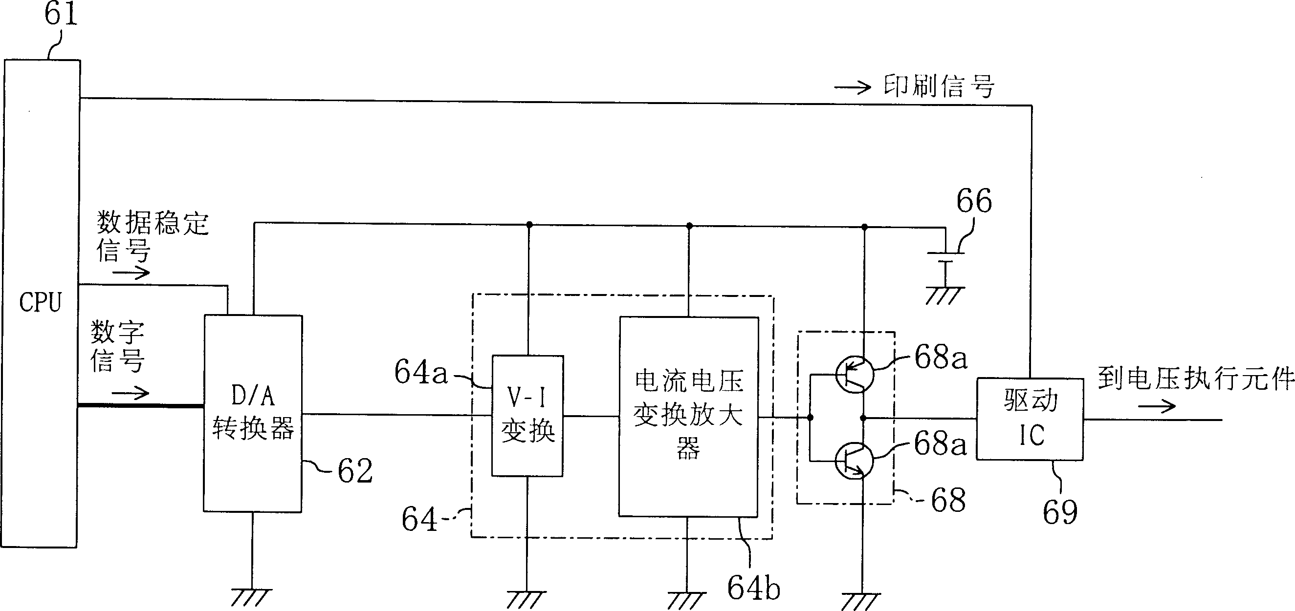
[0008] However, in the above-mentioned conventional waveform generating circuit, two D / A converters 102, 103 for generating a voltage rising waveform and a falling waveform are required, and because a positive voltage is supplied to the first D / A converter 102, a positive voltage is supplied to the second D / A converter 102, and Two D / A converters 103 provide negative voltages, but two power supplies 106, 107 that output positive and negative voltages are required, which will cause problems of high cost and considerable space
In addition, due to the characteristic difference (difference in offset) between the first and second D / A converters 102 and 103, errors will occur in the formed waveform.

Method used


Image

  • Ink jet head drive circuit and ink jet recording device
  • Ink jet head drive circuit and ink jet recording device
  • Ink jet head drive circuit and ink jet recording device

Examples


Embodiment Construction

[0035] best practice

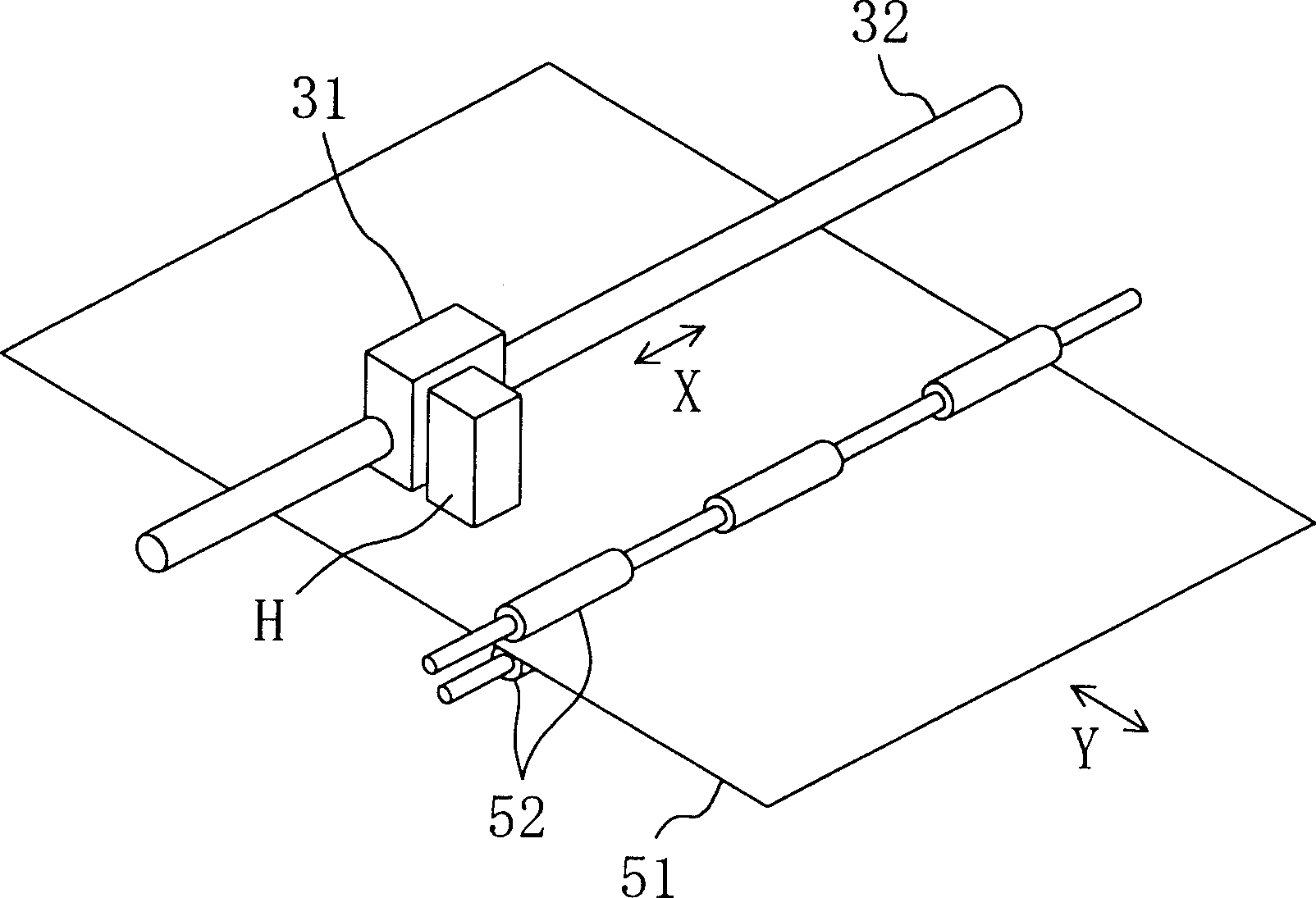
[0036] figure 1 The inkjet head type recording apparatus according to the embodiment of the present invention is shown as a schematic diagram. This inkjet head type recording device has an inkjet head H that ejects ink onto recording paper 51 as a recording medium, as will be described later. The inkjet head H is fixed and supported by the carriage 31; the carriage 31 is provided with a carriage motor, not shown; utilizing the carriage motor, the figure 1 The carriage shaft 32 extending in the X direction) makes the inkjet head H and the carriage 31 reciprocate along this direction. The carriage 31 , the carriage shaft 32 , and the carriage motor constitute a relative moving member that relatively moves the inkjet head H and the recording paper 51 .

[0037] The above-mentioned recording paper 51 is sandwiched between two conveying rollers 52 rotationally driven by a conveying motor not shown, and by the conveying motor and each conveying roller 52,...


PUM


Abstract

The present invention provides a waveform generating circuit, an inkjet head drive circuit and an inkjet head type recording device, which are arranged in the inkjet head drive circuit of the piezoelectric actuator 21 for driving the ejection ink in the inkjet head H. : a D / A converter 62 that converts a digital signal into an analog voltage and outputs it; the output voltage of the D / A converter 62 is input, and the output voltage of the above-mentioned D / A converter 62 is greater than the maximum value and the minimum value of the output voltage The waveform generation unit 64 generates a voltage rising waveform when the predetermined potential V2 in the middle of the value, and generates a voltage falling waveform when the output voltage of the D / A converter 62 is lower than the predetermined potential.

Description

technical field [0001] The present invention belongs to a waveform generating circuit for generating a voltage waveform, an inkjet head driving circuit for driving an inkjet actuator provided in an inkjet head, and an inkjet head having an inkjet head including an actuator driven by the inkjet head driving circuit The technical field related to head-type recording devices. Background technique [0002] In recent years, the inkjet head that has the actuator for ink ejection is well known, and the actuator of this inkjet head, for example, has the piezoelectric actuator that is equipped with electrodes respectively on both sides of the piezoelectric element, and it constitutes to hold the ink. part of the pressure chamber. By applying a pulse-like voltage to the electrodes of the actuator, the actuator is deformed, and the volume of the pressure chamber is also reduced, thereby generating pressure in the pressure chamber, and the pressure causes ink droplets to be ejected fro...

Claims


Application Information

Patent Timeline
Patent Type & Authority Patents(China)
IPC IPC(8): B41J2/045
CPCB41J2/04541B41J2/04548B41J2/04581B41J2/04588
Inventor 益本贤一宫宗宏昭大山正治
Owner PANASONIC CORP
Learn More