Converter circuit structure with direct voltage intermediate circuit

A converter circuit and intermediate circuit technology, applied in the field of power electronics, can solve problems such as impossible to drive rotating field motors, voltage spikes, etc.

Inactive Publication Date: 2005-09-07
ABB (SCHWEIZ) AG
View PDF3 Cites 0 Cited by
  • Summary
  • Abstract
  • Description
  • Claims
  • Application Information

AI Technical Summary

Problems solved by technology

Its disadvantage is that it is not possible to drive all types of rotating field motors: the switching process in the second converter results in non-sinusoidal voltages at the motor terminals, common-mode voltages between motor and ground due to capacitive grounding via filter capacitors causing voltage spikes between

Method used


Image

  • Converter circuit structure with direct voltage intermediate circuit
  • Converter circuit structure with direct voltage intermediate circuit
  • Converter circuit structure with direct voltage intermediate circuit

Examples


Embodiment Construction

[0015] The symbols used in the drawings and their meanings are listed in the symbol table.

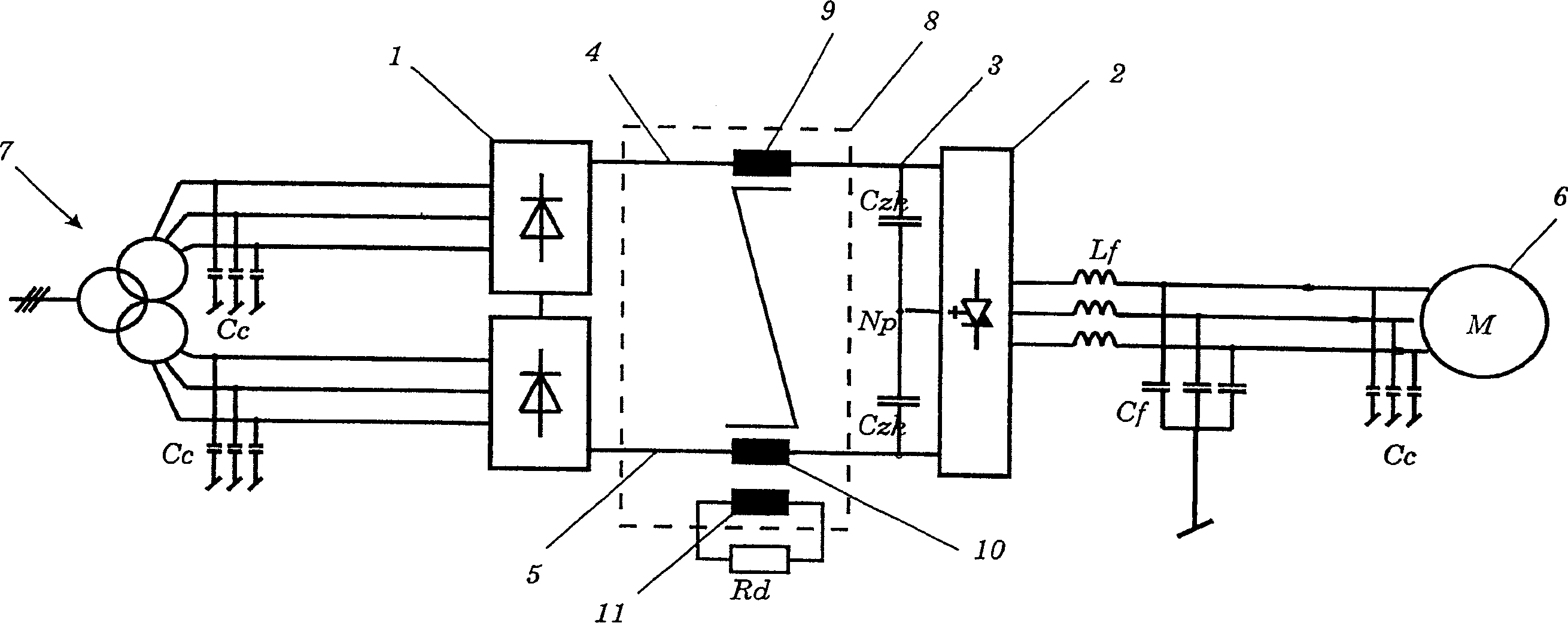
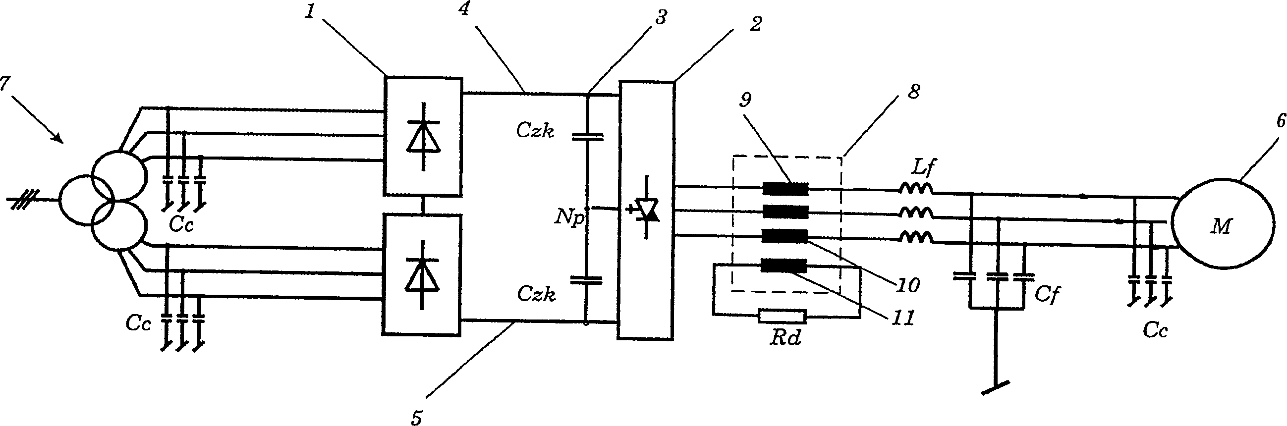
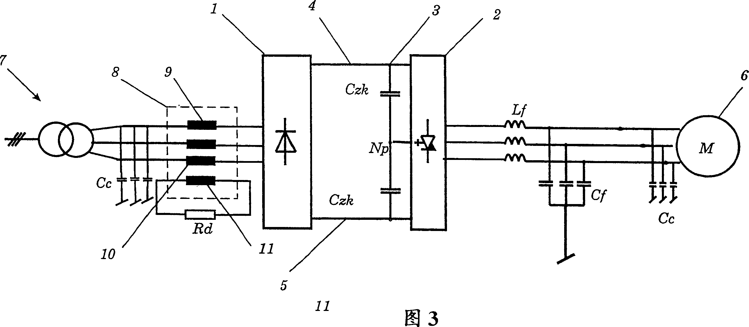
[0016] Referring now to the drawings, throughout which like reference numerals designate like or corresponding parts, figure 1 An exemplary embodiment of the invention is shown schematically. 7 denotes a three-phase voltage supply network connected to the first converter 1 via a main transformer. The three-phase shielded connection cable forms a cable inductance and a cable capacitance Cc, not shown. The AC voltage of the voltage supply network 7 is converted into a DC voltage in the converter 1 . The DC link circuit 3 comprises an link capacitor Czk, which is connected to the positive path 4 and the negative path 5 . The intermediate circuit 3 is connected to a second converter 2 which converts the DC voltage back to an AC voltage of variable frequency and amplitude.

[0017] In the exemplary embodiment shown, the second converter 2 is a three-point inverter. Therefore, two inter...


PUM


Abstract

The invention relates to a converter connection assembly with a direct voltage intermediate circuit (3) containing a transformer (8) with at least two windings (9 and 10). The transformer is connected in the intermediate circuit (3) in such a way that the undesired, asymmetric current components lead to a magnetization of the transformer core, and are thus suppressed. A grounded LC filter (Lf, Cf) is connected in front of the load (6). The filter effects a sinusoidal voltage on the load (6). As a result, the connection can be utilized with any polyphase machines and also during the expansion of existing systems.

Description

technical field [0001] The invention relates to the field of power electronics. It is a converter circuit structure. Background technique [0002] Converter circuit structures of this type are described, for example, in European patent applications EP 0 682 402 and EP 0 758 161 and in German laid-open specification DE 196 07 201 A1. Such a converter configuration has a first converter, which is preferably connected via a transformer to a three-phase voltage supply network. The first converter converts the AC voltage to DC voltage, but at the same time allows power to flow in both directions. The DC voltage supplies a DC intermediate circuit formed essentially by a bank of capacitors. The DC intermediate circuit is connected to a second converter driving a load, eg an electric motor. In particular, such an electric motor is a rotating field electric motor. Today, frequency converters with a DC intermediate circuit (U-converter) are commonly used to drive rotating field m...

Claims


Application Information

Patent Timeline
Patent Type & Authority Patents(China)
IPC IPC(8): H02J3/36H02M1/12H02M1/14
CPCH02M1/12
Inventor C·斯特姆勒C·斯图尔兹
Owner ABB (SCHWEIZ) AG
Why Eureka
Try Eureka