
Rotary connector

A technology for rotating connectors and connecting terminals, which is applied to flexible/rotatable wire connectors, connections, and parts of connecting devices, etc., and can solve problems such as mis-insertion, reversed left and right positions of two connectors, etc.

Inactive Publication Date: 2005-12-14
ALPS ALPINE CO LTD
View PDF0 Cites 0 Cited by
  • Summary
  • Abstract
  • Description
  • Claims
  • Application Information

AI Technical Summary

Problems solved by technology

[0013] However, in conventional rotary connectors, one guide block arranged straight along a straight line of the connecting terminal is inserted into two connectors respectively, so there is a problem that the left and right positions of the two connectors are reversed and wrong insertion occurs.

Method used


Image

  • Rotary connector
  • Rotary connector
  • Rotary connector

Examples


Embodiment Construction

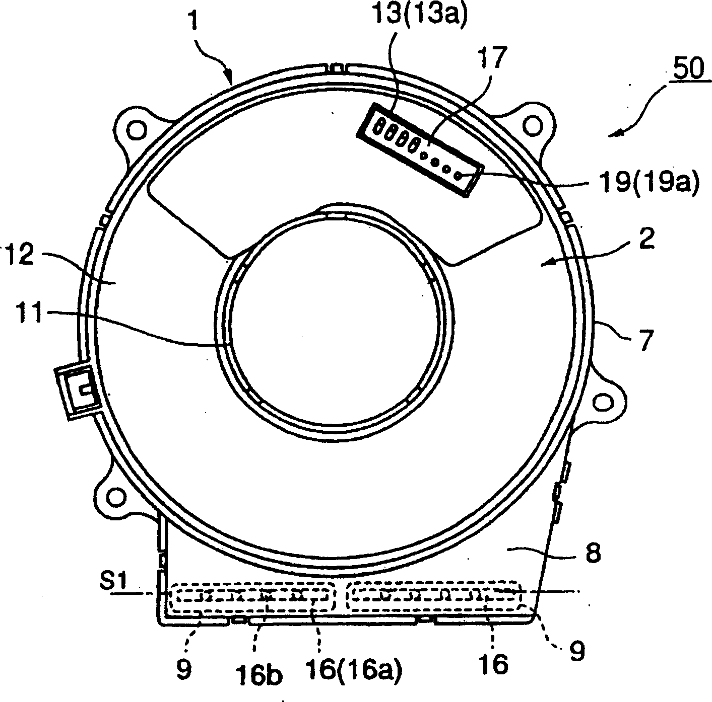
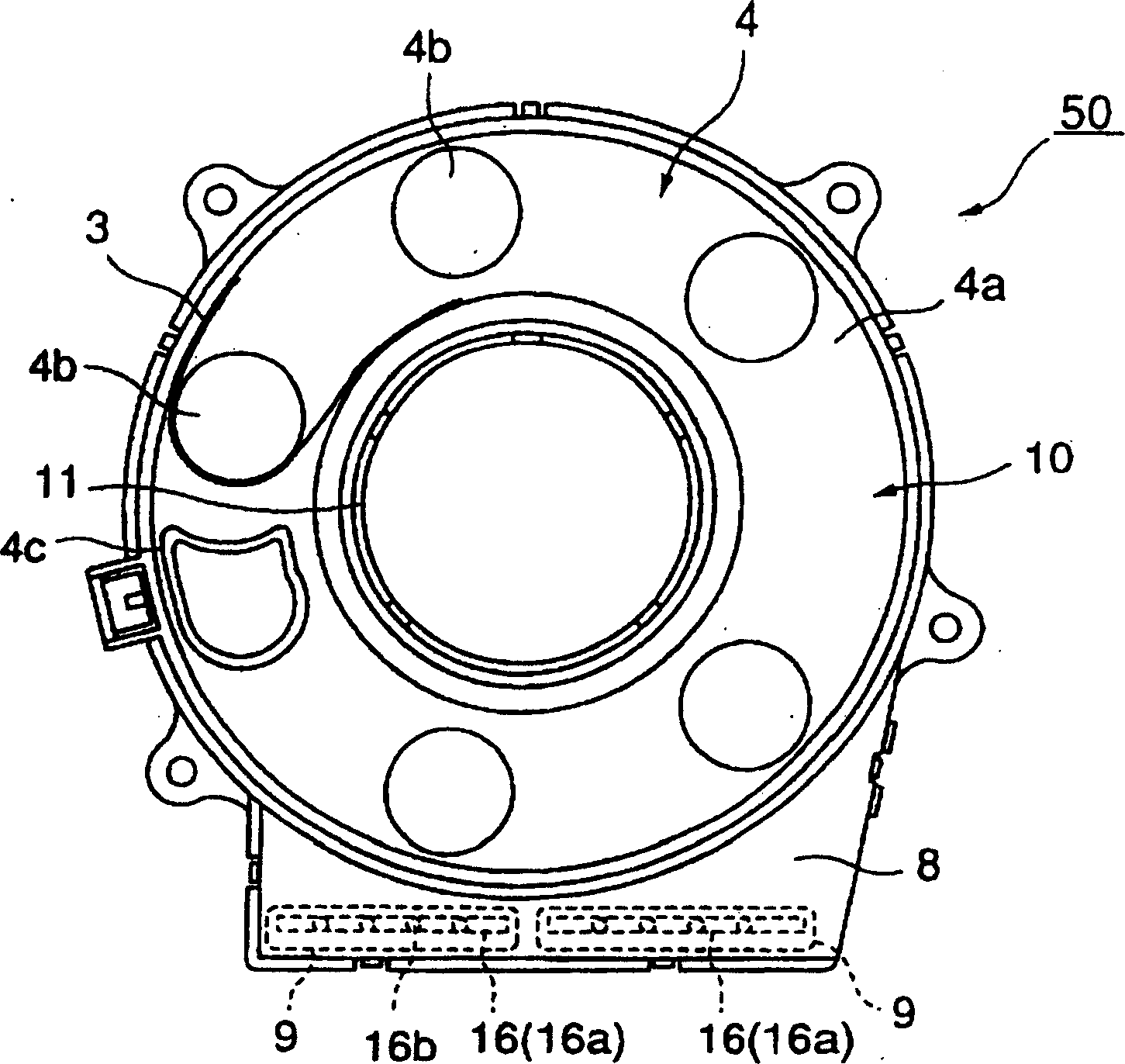
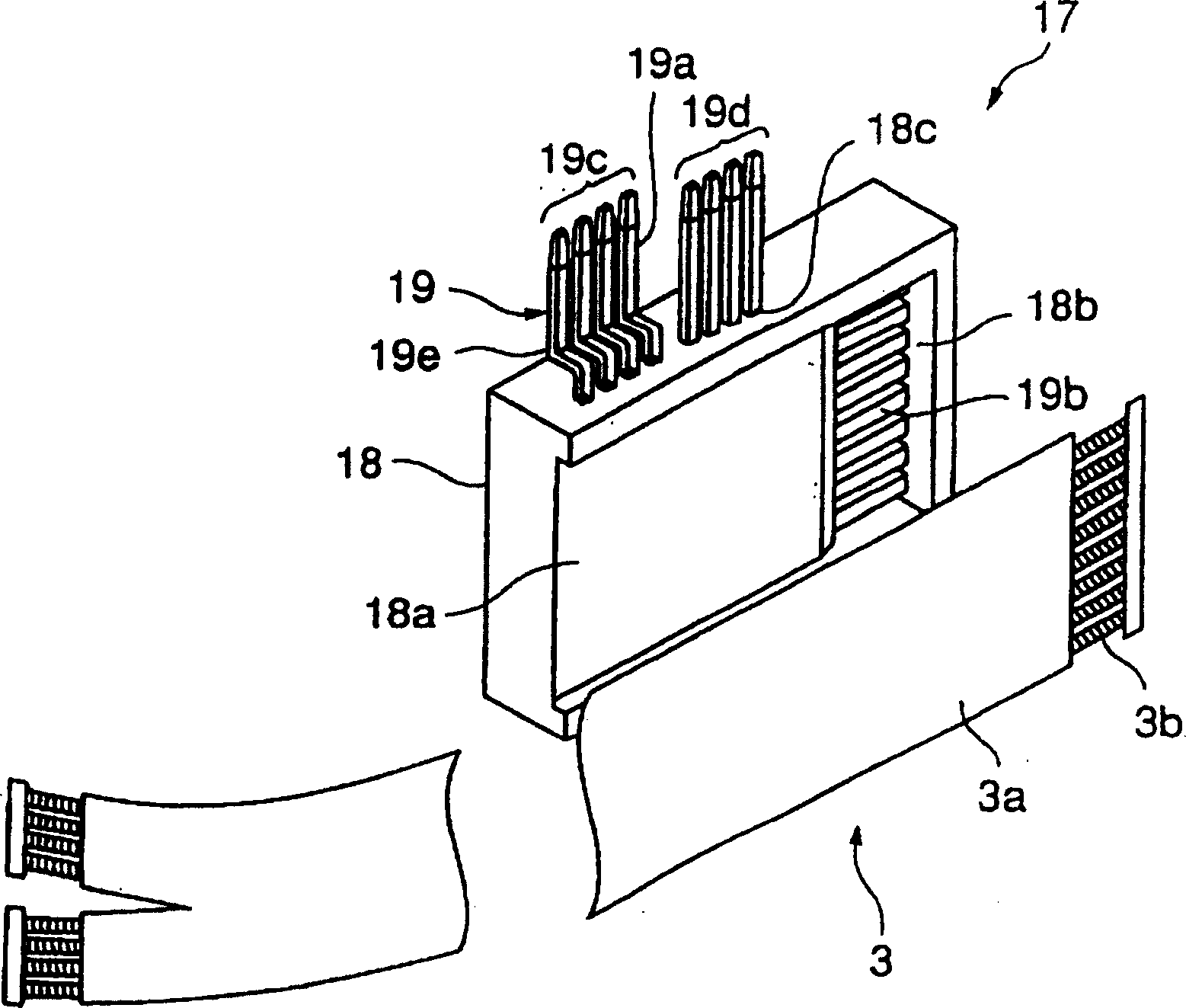
[0034] Below, the figure of a rotary connector is demonstrated. figure 1 is the top view of the rotary connector of the present invention, figure 2 It is a top view of the fixed casing and the movable body related to the rotary connector of the present invention, image 3 is a perspective view of the guide block and the flexible cable related to the rotary connector of the present invention, Figure 4 It is an explanatory diagram of the guide block and the accommodating part related to the rotary connector of the present invention, Figure 5 is along Figure 4 Sectional view of line 5-5.

[0035] The rotary connector 50 of the present invention is basically composed of the following parts: a fixed casing 1 , a rotatable movable motor casing 2 opposite to the fixed casing 1 , a connection formed between the fixed casing 1 and the movable motor casing 2 . The reelable cable 3 accommodated in the accommodating portion 10 , the movable body 4 that can freely rotate between t...


PUM


Abstract

A rotary connector, at least one of a first guide block and a second guide block (17) is equipped with a holding member (18), and a plurality of terminals (19a) protruding outward from the holding member ( 19), the plurality of terminals are connected to each end of the flexible cable (3), and at the same time, the plurality of terminals are at least composed of the first and second two-terminal groups (19c), (19d), arranged in parallel to each other On the first and second different straight lines (L1) and (L2) with predetermined intervals, the front ends of the connection terminals of the first and second terminal groups are arranged in parallel, respectively. In the past rotary connectors, the connection terminals were arranged straight. When inserting two connectors on a guide block arranged on a straight line, the positions of the two connectors may be reversed, sometimes causing the connectors to be inserted incorrectly. However, the present invention can provide a rotary connector so that each connector can be accurately inserted into a predetermined terminal.

Description

technical field [0001] The present invention relates to a rotary connector that is mounted on a driving device such as an automobile and used as an electrical connection device between a heating control device and an electrical device such as an airbag system mounted on a vehicle body. Background technique [0002] Hereinafter, the diagram of the conventional rotary connector will be described. Image 6 This is a plan view showing a conventional rotary connector. [0003] The rotary connector 60 is mounted on a steering device (not shown) of an automobile or the like, and is used as an electrical connection device for a heating control device circuit, a buffer air bag circuit, a horn circuit, and other switch circuits mounted on a steering wheel. It is basically composed of the following components: a pair of fixed casings 61 that are designed in concentric shapes and can be movably connected together relatively freely; a movable motor casing 62; formed between the pair of f...

Claims


Application Information

Patent Timeline
Patent Type & Authority Patents(China)
IPC IPC(8): B62D1/04B60R21/16H01R13/642H01R35/02H01R35/04H02G11/00
CPCH01R35/025
Inventor 荒木俊二
Owner ALPS ALPINE CO LTD
Learn More