Tensioning device for coil winder and controller for hysteresis braker

A technology of hysteresis brake and tensioning device, which is applied in the control of electromechanical brakes, coil manufacturing, control systems, etc., can solve the problems of inability to control the braking force, the braking force cannot be reduced to the target value, and the residual magnetic force cannot be completely eliminated. The effect of over-adjustment

Inactive Publication Date: 2006-03-15
TAGA MFG
View PDF2 Cites 0 Cited by
  • Summary
  • Abstract
  • Description
  • Claims
  • Application Information

AI Technical Summary

Problems solved by technology

Therefore, even if the application of the driving voltage to the hysteresis brake is reduced, the braking force cannot be reduced to the target value due to the residual magnetic force accumulated due to repeated braking operations, and the above-mentioned control device cannot perform accurate braking force control.
[0005] In addition, in JP-A-2002-101698, once the polarity reversal operation is performed instantaneously, overshoot occurs in the direction opposite to the braking direction of the hysteresis brake, so the residual magnetic force cannot be completely eliminated.

Method used


Image

  • Tensioning device for coil winder and controller for hysteresis braker
  • Tensioning device for coil winder and controller for hysteresis braker
  • Tensioning device for coil winder and controller for hysteresis braker

Examples


Embodiment 1

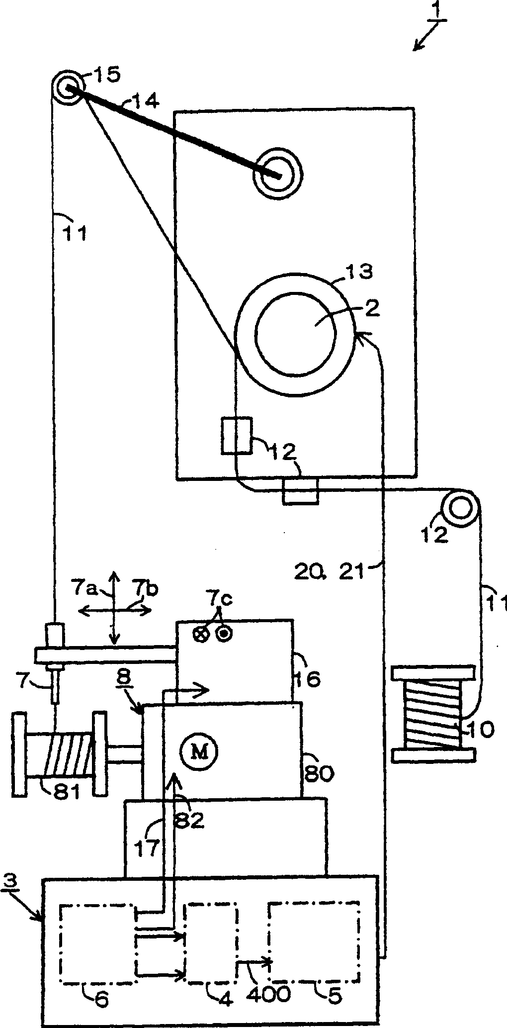
[0041] Hereinafter, for Embodiment 1 of the winding machine tensioning device of the present invention, according to figure 1 Go to FIG. 6 for description. In addition, the same code|symbol is attached|subjected to the member with the same meaning as a conventional example, and detailed description is abbreviate|omitted.

[0042]The structure of the take-up device 1 for a winding machine of the present invention is to include a take-up roller 13 for winding a wire 11, a hysteresis brake 2 for supplying rotation resistance to the take-up roller, and a wire 11 pulled out from a wire storehouse 10 to pass through the guide roller 13. The device 12 is wound on the take-up roller 13 of the hysteresis brake 2, passes through the roller 15 at the front end of the take-up arm 14, and is wound on the bobbin 81 driven by the motor 80 of the winding machine main body 8 through the nozzle 7 .

[0043] In addition, a control device 3 for controlling the hysteresis brake 2 and making the...

Embodiment 2

[0076] Hereinafter, Embodiment 2 to which the tensioning device of the wire winding machine of Embodiment 1 is applied will be described, and descriptions that are the same as those in Embodiment 1 will be given the same symbols and detailed descriptions will be omitted.

[0077] The tensioning device 1 of the wire winding machine of the second embodiment has the control device 3 for controlling the hysteresis brake 2a and forming a fixed tensioning corresponding to the winding state similarly to the first embodiment.

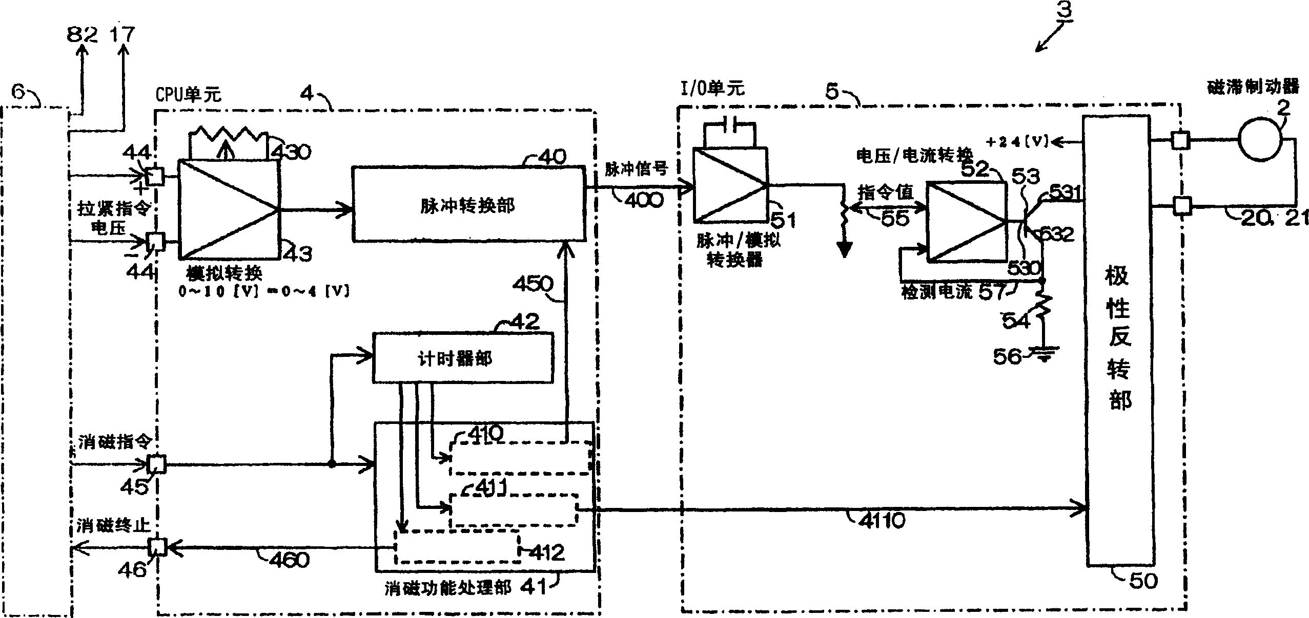
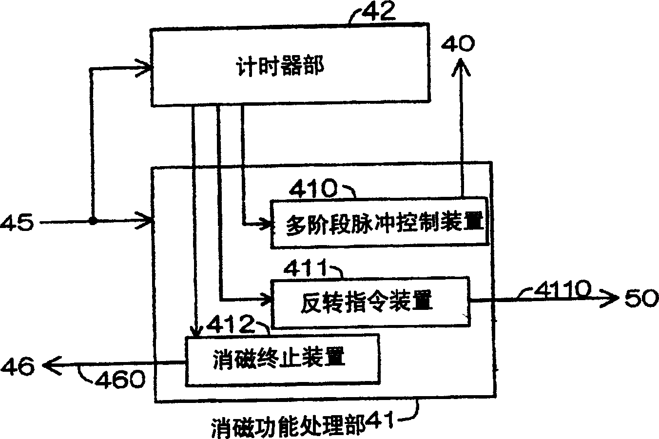
[0078] The control device 3 includes an NC control device 6 , a CPU unit 4 , and an I / O unit 5 .

[0079] The CPU unit 4 has the same configuration, control method, etc. as those in Embodiment 1, and therefore description thereof will be omitted.

[0080] The I / O unit 5 is configured such that a hysteresis brake selection unit 58 is connected to the output side of the pulse / analog conversion circuit 51 , and a voltage / current converter 52 is connected to the ou...


PUM


Abstract

Tension apparatus of winding machine and control device for hysteresis brake. A kind of tension apparatus of winding machine, which is capable of controlling the tension of wiring material to have a constant tension based on the winding condition even the rotation speed of winding machine body is changed abruptly, is provided in the present invention. In addition, a control apparatus capable of conducting highly precise and stable break control is provided. The invented tension apparatus (1) of winding machine is provided with the control apparatus (3) that is composed of CPU unit (4), I / O unit (5), and NC control apparatus (6). The CPU unit (4) is provided with the followings: a pulse conversion portion (40), which converts the tension command voltage (44) that forms the threshold added voltage of the hysteresis break (2) into a pulse shape; the demagnetization treatment portion (41) for eliminating the accumulated residual magnetism due to the hysteresis break (2); and the timer portion (42) for calculating the demagnetization time. The I / O unit (5) is provided with a polarity reversion portion (50) for reversing the added demagnetization voltage of the hysteresis break (2).

Description

technical field [0001] The present invention relates to a coiler tensioning device and a hysteresis brake control device for controlling tension of a wire supplied to a coiler. Background technique [0002] The tensioning device of the existing winding machine is disclosed in Japanese Patent Application Laid-Open No. 64-41207, for example. The structure in this tensioning device 1 is, as Figure 8 As shown, the wire 11 pulled out from the wire warehouse 10 is wound on the tension roller 13 of the hysteresis brake 2 through the guide device 12, and is wound on the tension roller 13 of the tension arm 14 front end by the winding machine main body 8. The motor 80 drives the bobbin 81. On the basis of the above structure, a tension control device 9 for the purpose of fixing the tension of the wire 11 is also disclosed. The tension control device 9 includes a control device for a driving motor 80 of the bobbin 81 , outputs a motor control signal 82 to the motor 80 , and supplie...

Claims


Application Information

Patent Timeline
Patent Type & Authority Patents(China)
IPC IPC(8): H01F41/06H02P15/00B65H54/00B65H59/38
CPCB65H59/16B65H2403/725B65H2557/33B65H2557/352
Inventor 中野健二中谷荣一
Owner TAGA MFG
Why Eureka
Try Eureka