
Buckle

A technology of components and strips, which is applied in the field of buckles, can solve the problems of insufficient clamping force of the belt, inability to reliably prevent the movement of the belt, and the decline of the fixing function, so as to achieve easy fixing and moving operations, less damage, and prevent the fixing function Falling effect

Inactive Publication Date: 2006-03-29
YKK CORP
View PDF2 Cites 0 Cited by
  • Summary
  • Abstract
  • Description
  • Claims
  • Application Information

AI Technical Summary

Problems solved by technology

[0009] Conversely, if the distance between the engaging protrusion of the stopper and the winding shaft is much greater than the thickness of the belt, the force to clamp the belt is insufficient, and the movement of the belt cannot be reliably prevented.
[0010] In addition, if it is used repeatedly for a long time, the engagement protrusion of the stopper becomes easy to slip due to wear and other reasons, and there is a problem that the belt cannot be reliably prevented from moving.
That is, wear tends to cause deterioration of the fixing function

Method used


Image

  • Buckle
  • Buckle
  • Buckle

Examples


Embodiment Construction

[0045] Embodiments of the present invention will be described below with reference to the drawings.

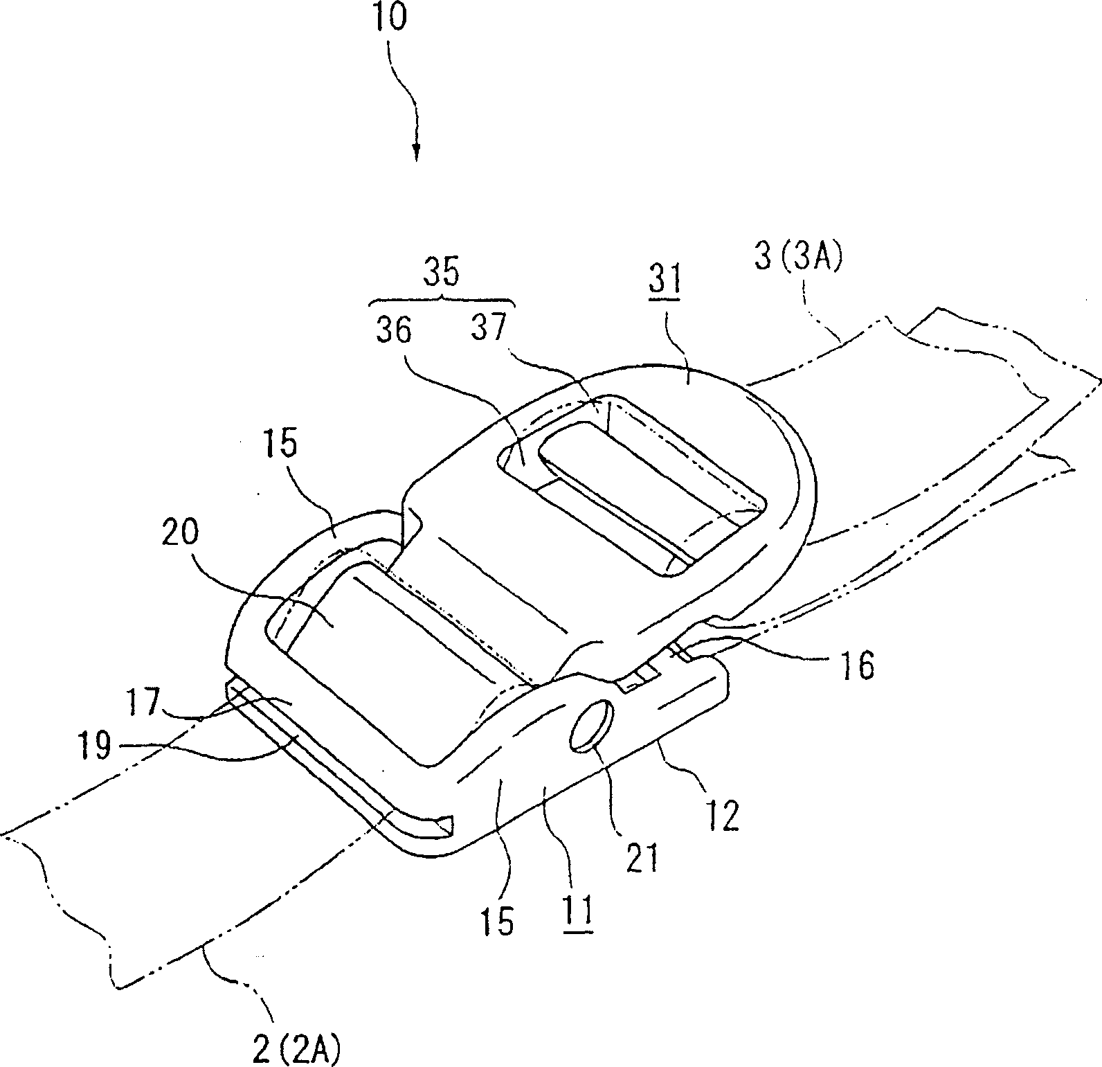
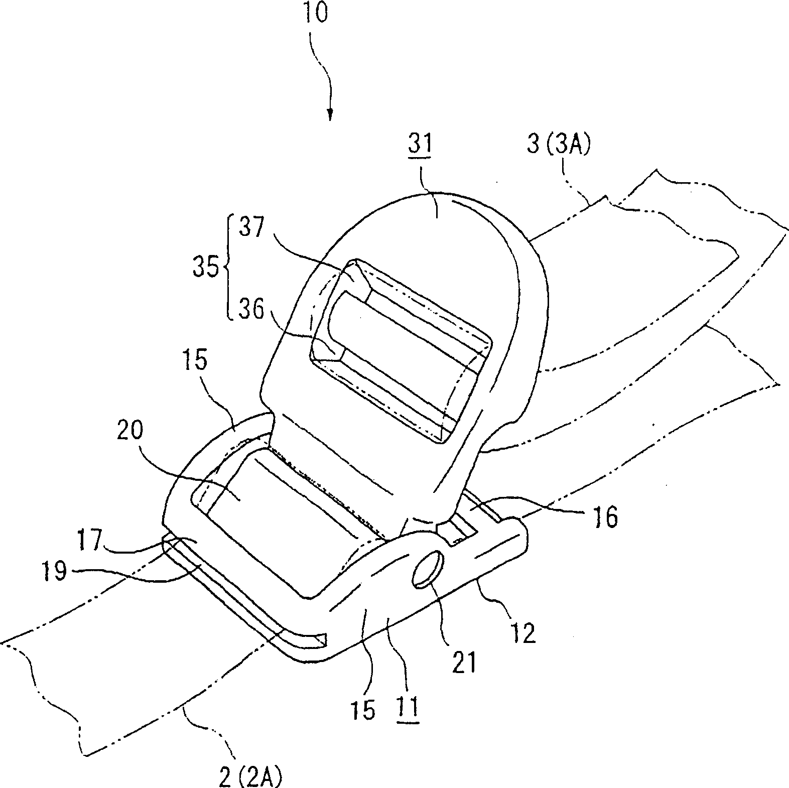
[0046] figure 1 and figure 2 The clasp (fixed state and unfixed state) 10 of this embodiment is shown. The buckle 10 in the above Figure 8 and Figure 9 In the structure of the rucksack, it is suitable for the position of the connector 3D, and has the function of moving the belt 2 (2A) as a belt in the length direction and can be fixed at any position and can adjust the belt 3 ( 3A) Function of length. The belts 2 and 3 are synthetic resin yarns made of plain weave, mountain cedar weave, grosgrain weave, basket weave, deformed basket weave, etc., which have a certain degree of body (rigidity) and are formed into a predetermined width. Ribbon.

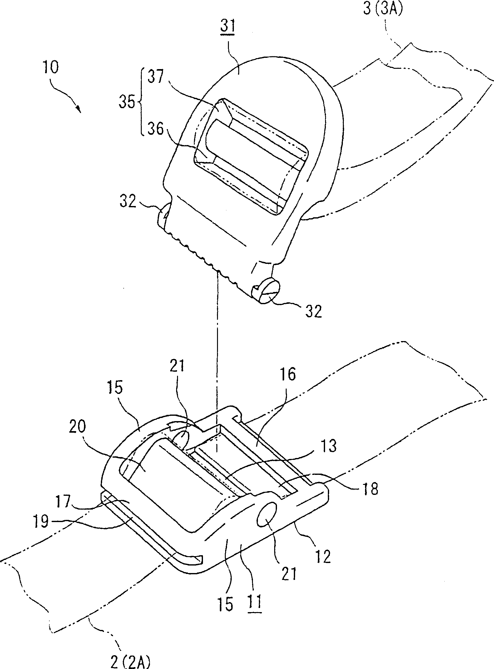
[0047] The buckle 10 of this implementation form is as image 3 and Figure 4 As shown, there is a buckle body 11 as a first member made by injection molding of synthetic resin, and an engaging member 31 as a second member pro...


PUM


Abstract

Provided is a buckle which comprises a buckle main body 11 and an engagement member 31. The buckle main body 11 comprises a base part 12, at least two insertion holes 18 and 19 provided on the base part 12 with a space in between, to which a belt 2 is inserted, and an upstanding piece 20 provided therebetween for bending the belt 2 in a direction away from the base part 12. The engagement member 31 can be moved to a first position where the buckle can be moved against the belt 2 and to a second position where the buckle can be fixed to the belt 2. Further, the engagement member 31 comprises a pressurizing part 33 for pressurizing the belt 2 in the second position so as to obtain a further bent state and an adjustor 35 capable of adjusting the length of the other belt 3.

Description

technical field [0001] The present invention relates to a buckle. Specifically, it relates to a buckle that is movable in the longitudinal direction of a belt and can be fixed at an arbitrary position. Background technique [0002] In the past, as a buckle that includes a first member and a second member that is movably arranged on the first member, can move in the longitudinal direction of the strip and can be fixed at any position, for example, there is a buckle disclosed in Japanese Patent Application Publication No. 5-31926 Publication No. 1 (Prior Art Example 1) or the button disclosed in Japanese Utility Model Publication No. 4-9841 (Prior Art Example). [0003] The buckle of prior art example 1 has a buckle body and a stop piece. The buckle body has a pair of side frames, a mounting shaft on one end side of the pair of side frames, and a winding shaft and a guide shaft on the other end side of the pair of side frames. One end side of the stop piece is rotatably sup...

Claims


Application Information

Patent Timeline
IPC IPC(8): A44B11/12
CPCA44B11/12Y10T24/4079Y10T24/2175Y10T24/4773Y10T24/4072Y10T24/4016Y10T24/4019A44B11/25
Inventor 上原亮一郎杵渊真一郎高桥义信
Owner YKK CORP
Learn More