Tampon applicator tube having apertured finger grip

A finger and tampon technology, applied in the field of tubular insertion devices, can solve the problems of inability to provide

Inactive Publication Date: 2000-06-28
MCNEIL PPC INC
View PDF6 Cites 4 Cited by
  • Summary
  • Abstract
  • Description
  • Claims
  • Application Information

AI Technical Summary

Problems solved by technology

[0005] In view of the above-mentioned shortcomings of the prior art, there is a need for a tampon applicator that substantially prevents finger slippage during insertion of the device, ejection of the substantially closed ...

Method used


Image

  • Tampon applicator tube having apertured finger grip
  • Tampon applicator tube having apertured finger grip
  • Tampon applicator tube having apertured finger grip

Examples


Embodiment Construction

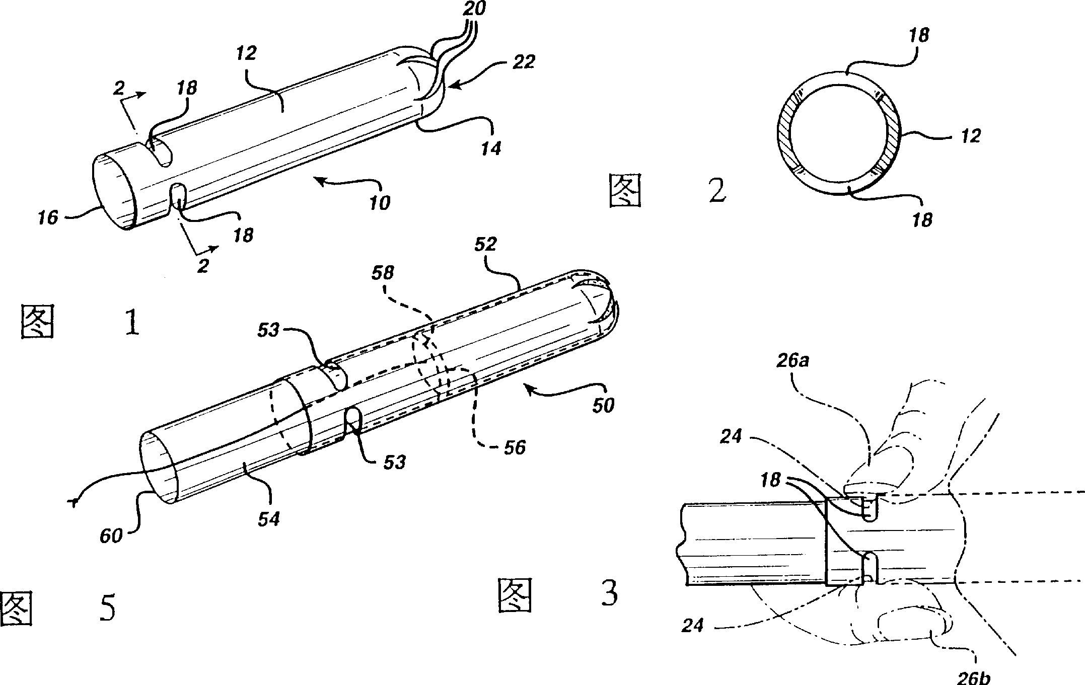
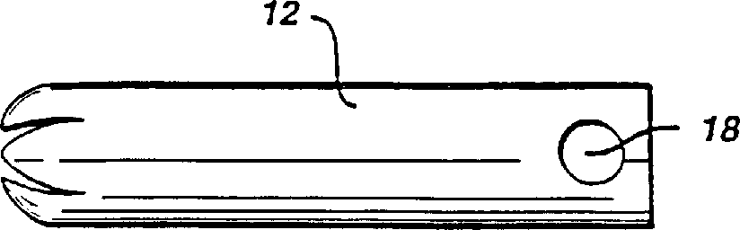
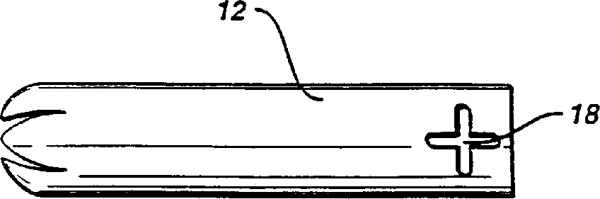
[0019] Referring to FIGS. 1-3 , one embodiment of the present invention relates to a tampon applicator tube 10 forming a tubular member 12 having an insertion end 14 and a gripping end 16 . Gripping end 16 has a plurality of finger receiving holes 18 . Insertion end 14 has a plurality of inwardly curved lobes 20 to form a generally closed dome.

[0020] The finger-receiving aperture 18 at the gripping end is sized to receive a portion 24 of a user's finger 26 . Experimentation has shown that the useful longitudinal dimension of the aperture 18 can vary from 1 mm or less to greater than 10 mm. The useful circumferential dimension of the bore 18 varies from about 1 mm to greater than 20 mm. Preferably the longitudinal dimension is from about 1 mm to about 10 mm, more preferably from about 6 mm to about 8 mm. Preferably the circumferential dimension is from about 3mm to about 20mm, more preferably from about 8mm to about 16mm. If the hole size is too long, the tube loses the ...


PUM


Abstract

The present invention relates to an insertion device formed of a tubular element capable of substantially containing an insertable element. The tubular element has an insertion end and a gripper end. The gripper end has a plurality of finger-accepting apertures. These apertures are dimensioned to accept a portion of a user's finger. This device is particularly useful in a tampon applicator tube which has a high-gloss outer surface.

Description

field of invention [0001] The present invention relates to tubular insertion devices having apertures in the finger grips to enhance the user's ability to securely grip the placement tube during use. More specifically, the insertion device has a plurality of finger receiving holes at the gripping end of the tube. Background of the invention [0002] Tubular insertion devices such as tampon applicators are generally made of one of two basic materials, plastic and cardboard. Devices, whether made of plastic or cardboard, generally have some surface feature at their trailing or gripping end to allow the user to grip the applicator loosely or tightly during the following actions: Inserting the device, expelling a substantially closed element from the device, withdrawing the device. Attempts have been made to add surface treatments to the gripping end of tampon applicator tubes in plastic and cardboard devices. For example, U.S. Patent No. 4,412,833 to Wiegner et al. discloses...

Claims


Application Information

Patent Timeline
IPC IPC(8): A61F13/32A61F13/26
CPCA61F13/26
Inventor A·J·哈格尔蒂
Owner MCNEIL PPC INC
Why Eureka
Try Eureka