Unlock instant, AI-driven research and patent intelligence for your innovation.

Socket

A technology for sockets and sockets, applied in the direction of the base/housing, electrical components, coupling devices, etc., can solve the problems of insufficient insulation distance, insufficient strength, troublesome assembly operations, etc.

Inactive Publication Date: 2006-05-31
PANASONIC CORP
View PDF0 Cites 0 Cited by
  • Summary
  • Abstract
  • Description
  • Claims
  • Application Information

AI Technical Summary

Problems solved by technology

[0003] However, the charging part and the metal assembly frame that is not a charging part are arranged relatively close to each other, and the insulating distance between the non-charging part such as the assembly frame and the charging part may not be sufficiently large.
In addition, in the assembly of the body, the assembly work is cumbersome due to the use of the assembly frame.
Further, since the assembly frame is configured across the front of the body, if the size of the assembly frame is increased without reducing the area where the insertion portion at the front of the body is provided, its strength will not be sufficient.
[0004] On the other hand, when fitting the assembling claws of the main body into the assembling holes of the cover, the assembling piece must be bent. If the cover with the insertion part is formed of a synthetic resin with anti-leakage property, the mechanical strength is not enough, and there are problems during assembly. Defects such as damage to the assembly sheet may occur

Method used


Image

  • Socket
  • Socket
  • Socket

Examples


Embodiment 1

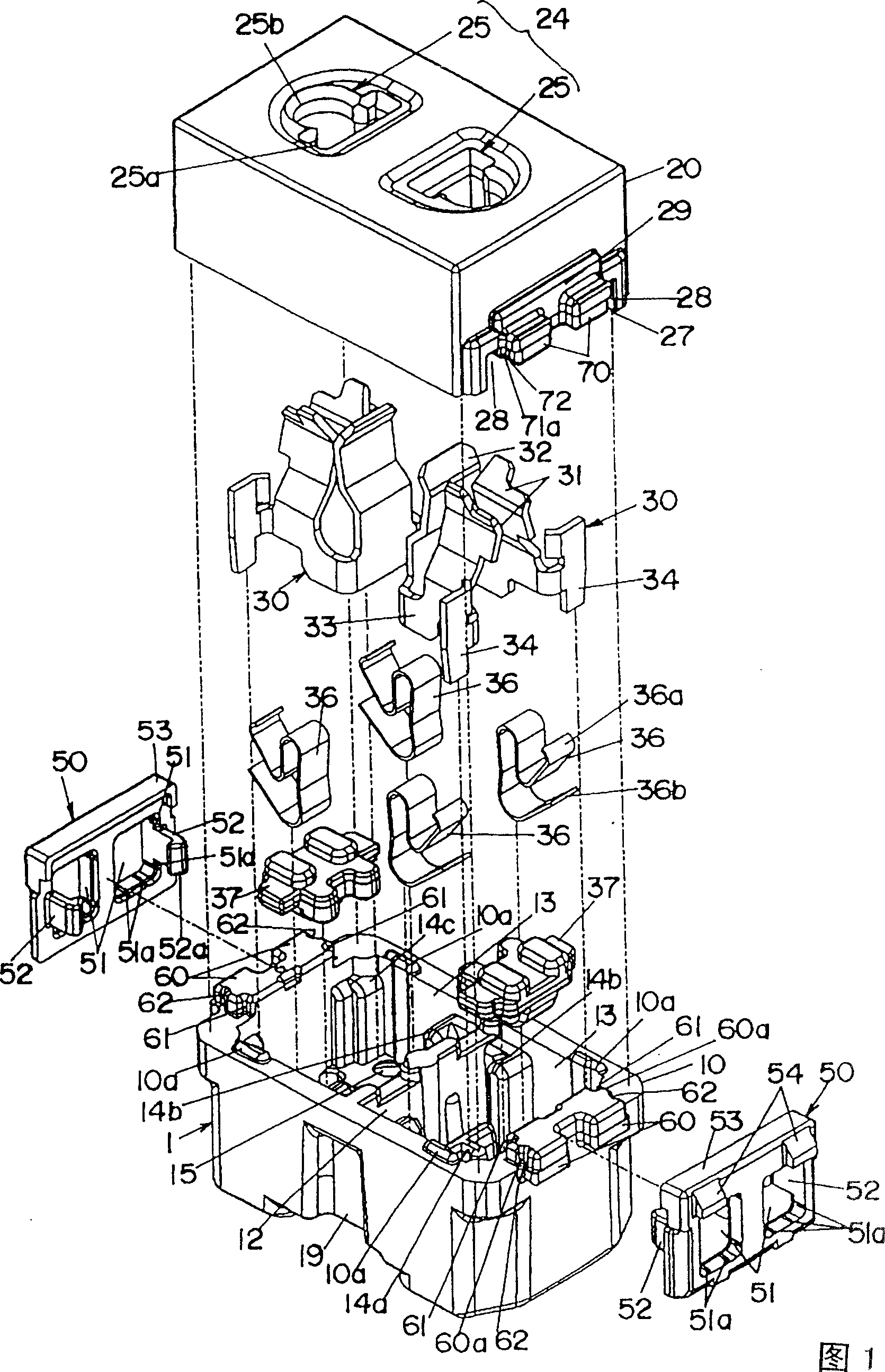
[0113] The structure of this embodiment is shown in Figures 1-6. The body 1 is formed by adopting a thermosetting synthetic resin (for example, urea resin) excellent in leakage resistance to form a rectangular main body 10 with an open front, and using a thermosetting synthetic resin (for example, urea resin) excellent in leakage resistance to form a rectangular body 10 with an open back. The rectangular cover 20 is combined. The body 1 has predetermined unit dimensions described later.

[0114] The main body 10 divides the internal space into two by the partition wall 12 provided in the middle in the longitudinal direction. A positioning convex portion 10 a protruding forward is protruded from an appropriate place on the peripheral wall of the main body 10 . The positioning protrusions 10a fit into recesses (not shown) formed on the cover 20 when the body 10 and the cover 20 are combined to prevent the body 10 and the cover 20 from shaking. In addition, a partition wall (n...

Embodiment 2

[0147] Figure 23 An exploded perspective view of this embodiment is shown in Figure 24 Respectively represent its front view and top view. Since the basic configuration of this embodiment is the same as that of Embodiment 1, the same symbols are used for the same configurations and their descriptions are omitted, and only the characteristic configurations of this embodiment will be described.

[0148] The feature of this embodiment is that a total of four clamping pins 52 protrude from the four corners on the back side to the back side at positions on multiple diagonal lines of the fitting parts 60 and 70 that clamp the assembly frame 50, At the same time, the locking claw 52 a of each locking leg 52 protrudes from the side opposite to the fitting portion 60 , 70 . That is to say, on the rear side of the assembly frame 50 facing the device body 1 on the back side of the assembly frame 50 in the front and rear direction, the slightly central parts of the left and right ends...

Embodiment 3

[0152] Figure 26 27 shows its front view, bottom view and a part of right sectional view respectively. Since the basic configuration of this embodiment is the same as that of Embodiment 1, the same symbols are used for the same configurations and their descriptions are omitted, and only the characteristic configurations of this embodiment will be described.

[0153] The feature of this embodiment is that the clip pins 52 of the assembly frame 50 are connected from the front and back direction of the body 1 (the connection direction of the body 10 and the cover 20, Figure 26 In the Y-axis direction), the slightly central positions in the left and right directions opposite to each other protrude toward the back side. That is, on the rear side of the assembly frame 50 facing the device body 1 in the embodiment 1, the front and rear direction slightly central parts of the left and right ends of the assembly frame 50 protrude to the back side respectively. In this structure, for...


PUM


Abstract

To provide a socket whose body is formed of a synthetic resin that is difficult to damage and has leakage resistance like thermosetting resin, and which can increase the size of the insertion part surface of the body compared with the case of using a metal assembly frame, by The assembly frame made of synthetic resin is concavo-convexly fitted in the fitting parts provided on both the body and the cover to connect the body and the cover. Since the body and cover are connected by a synthetic resin assembly frame, the body and cover can be formed of a synthetic resin that is difficult to damage and has leakage resistance like thermosetting resins, and can increase compared with the case of using a metal assembly frame. The size of the surface to set the insertion part of the device body large.

Description

technical field [0001] The present invention relates to a socket constructed by embedding a part thereof in a construction surface such as a wall surface. Background technique [0002] Generally, when the socket is manufactured, a charging member such as a receiving member for receiving a plug knife is accommodated in the body, and then a body and a cover of a synthetic resin molded product are combined to form the body. In order to assemble the body and cover that constitute the body, there is a method of using a metal assembly frame, or a method of fitting an assembly claw provided on the body with a concave-convex fit in an assembly hole of an assembly piece provided on the cover. [0003] However, the charging member and the non-charging member metal assembly frame are arranged relatively close to each other, and the insulating distance between the non-charging member such as the assembly frame and the charging member may not be sufficiently large. Also have, owing to h...

Claims


Application Information

Patent Timeline
IPC IPC(8): H01R25/00H01R13/46H01R13/52
Inventor 野村秀和立石博之坂部正司本田稔草间公男铃木健
Owner PANASONIC CORP