Cathode-ray tube with erasing coil capable of minimizing electronic beam change on screen

A technology for cathode ray tubes and degaussing coils, which is applied in the direction of cathode ray tubes/electron beam tubes, circuit components of time-of-flight electron tubes, discharge tubes, etc., which can solve problems such as lowering productivity and obstacles in degaussing coils, and improve productivity Effect

Inactive Publication Date: 2006-08-23
SAMSUNG SDI CO LTD
View PDF1 Cites 0 Cited by
  • Summary
  • Abstract
  • Description
  • Claims
  • Application Information

AI Technical Summary

Problems solved by technology

However, when a CRT having such a structure is used in an actual TV set, a computer monitor, etc., the degaussing coil becomes an obstacle when the CRT is installed in a component accommodating the CRT, such as a TV case.
As a result, productivity was reduced during the manufacture of the components housing such CRTs

Method used


Image

  • Cathode-ray tube with erasing coil capable of minimizing electronic beam change on screen
  • Cathode-ray tube with erasing coil capable of minimizing electronic beam change on screen
  • Cathode-ray tube with erasing coil capable of minimizing electronic beam change on screen

Examples


Embodiment Construction

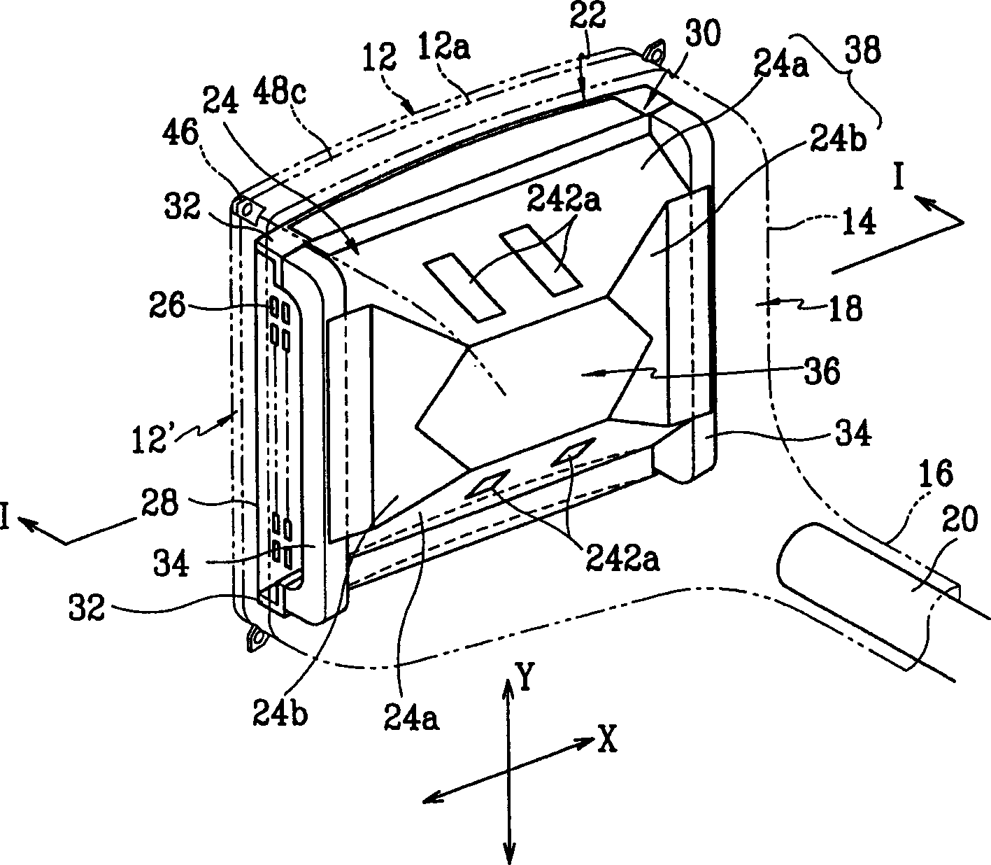
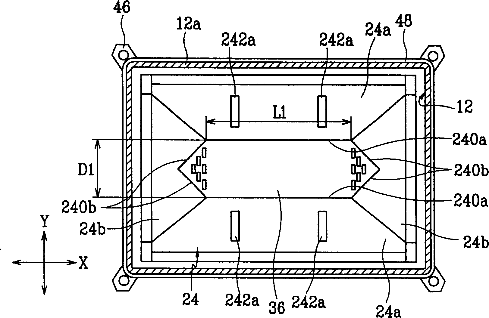
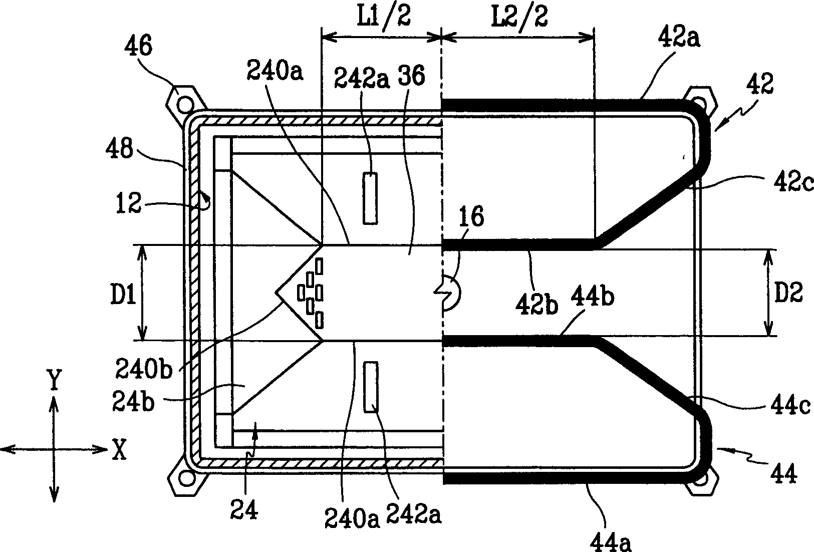
[0027] figure 1 is a schematic perspective view for explaining the internal structure of the cathode ray tube according to the embodiment of the present invention, figure 2 is along the figure 1 A cross-sectional view taken on line I-I, and image 3 is as from figure 2 The same perspective view of figure 1 A half-section view of a cathode ray tube.

[0028] As shown, the exterior of the cathode ray tube (CRT) according to the first embodiment of the present invention is defined by the faceplate 12 , the cone 14 and the neck 16 , which are fused into an integral unit to form the tube 18 . The tube 18 is evacuated to achieve a vacuum between 10-7 and 10-10 Torr.

[0029] The panel 12 includes: a front surface forming a phosphor screen (not shown) including RGB phosphors; and a skirt 12a extending from the outer periphery of the front surface of the panel 12 toward the cone 14 . An electron gun 20 is mounted in the neck 16 . The electron gun 20 emits electron beams to th...


PUM


Abstract

A cathode ray tube includes a tube having a panel, a funnel, and a neck, a color selection apparatus mounted to the panel within the tube, an inner shield connected to the color selection apparatus. The inner shield includes a plurality of side walls that form a center opening through which electron beams pass, and at least one degaussing coil mounted at outer surface of the tube. The degaussing coil includes a first coil mounted toward the panel, a second coil mounted toward the neck, and a third coil connected to ends of the first coil and the second coil to interconnect the first coil and the second coil. The second coil is mounted on the tube in a state substantially overlapping distal edge portions of the side walls of the inner shield on which the second coil is mounted.

Description

technical field [0001] The present invention relates to a cathode ray tube, and more particularly, to a cathode ray tube employing a degaussing coil for demagnetizing metal parts in the cathode ray tube, such as a color selector and an inner shield. Background technique [0002] Metal parts such as color selectors and inner shields are common in cathode ray tubes (CRTs). The color selection device includes a shadow mask and a shadow mask frame, the shadow mask having a plurality of holes for performing color separation of three electron beams, the three electron beams being corresponding R, G, B phosphors emitted from the electron gun to the phosphor screen, the shadow mask The mask frame is used to firmly support the shadow mask at a predetermined position in the CRT. The inner shield performs the function of shielding the path over which the electron beam travels from the earth's magnetic field. [0003] However, the metal parts are still magnetized by the earth's magnet...

Claims


Application Information

Patent Timeline
Patent Type & Authority Patents(China)
IPC IPC(8): H01J29/00H01J31/12H01J23/16H01J29/06
CPCH01J29/003H01J2229/0053
Inventor 禹德珍宋正锡金成燮
Owner SAMSUNG SDI CO LTD
Why Eureka
Try Eureka