Radio communication terminal and transmission power control method

A technology for transmission power control and wireless communication terminals, which is applied in wireless communication, power management, and device selection, and can solve problems such as increased interference from other surrounding terminal devices, shortened battery life, and inability to communicate with other surrounding terminal devices

Inactive Publication Date: 2000-11-29
PANASONIC CORP
View PDF0 Cites 3 Cited by
  • Summary
  • Abstract
  • Description
  • Claims
  • Application Information

AI Technical Summary

Problems solved by technology

[0019] In this case, since the above-mentioned conventional terminal equipment considers the attenuation in the propagation path even when the received signal is lowered due to the deviation of the directionality, and transmits the signal with excess power, the interference to other nearby terminal equipment The amount of power increases, so that other surrounding terminal devices cannot communicate, and the battery life is shortened

Method used


Image

  • Radio communication terminal and transmission power control method
  • Radio communication terminal and transmission power control method
  • Radio communication terminal and transmission power control method

Examples


Embodiment 1

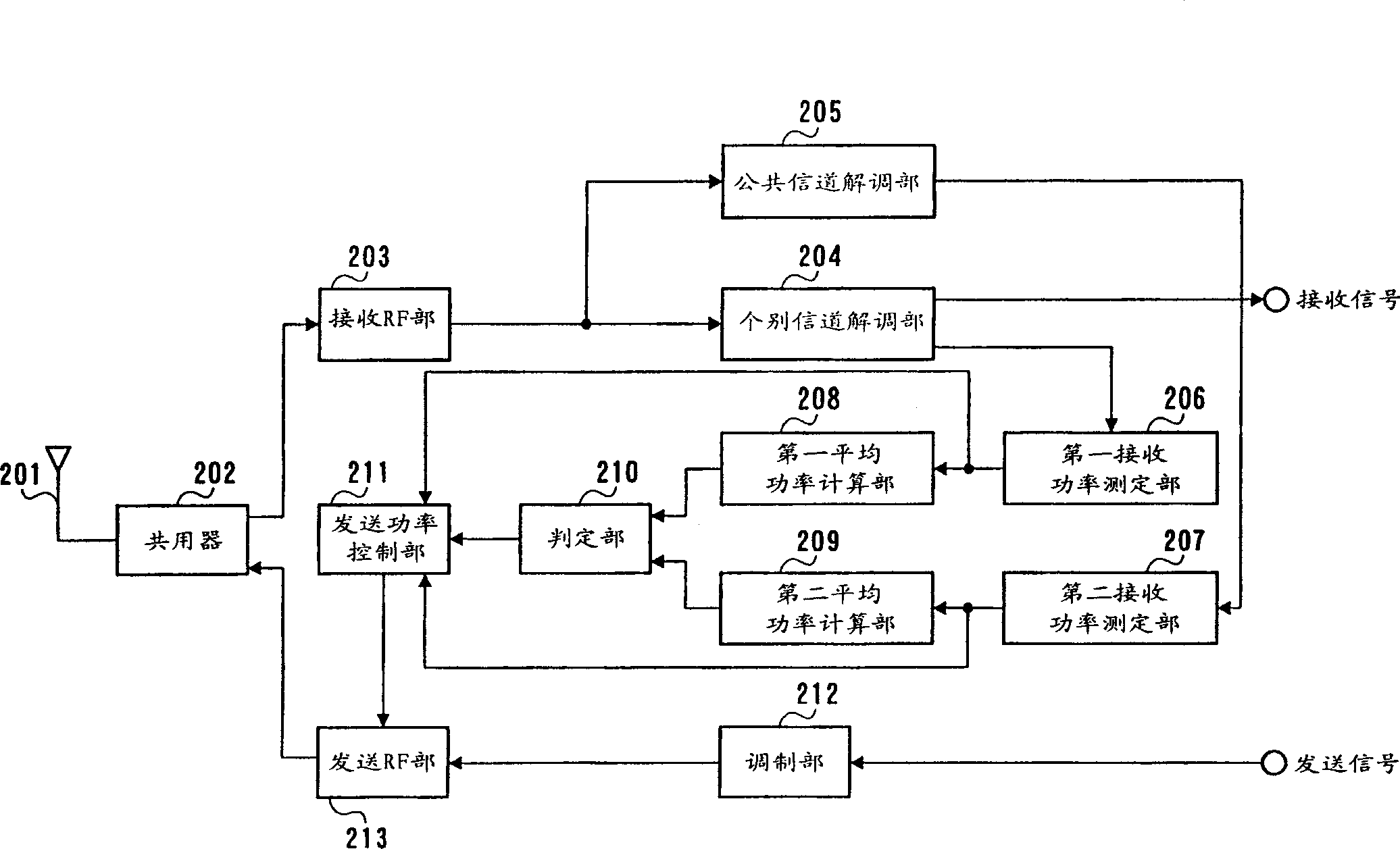
[0035] image 3 It is a block diagram showing the structure of the terminal device of the first embodiment.

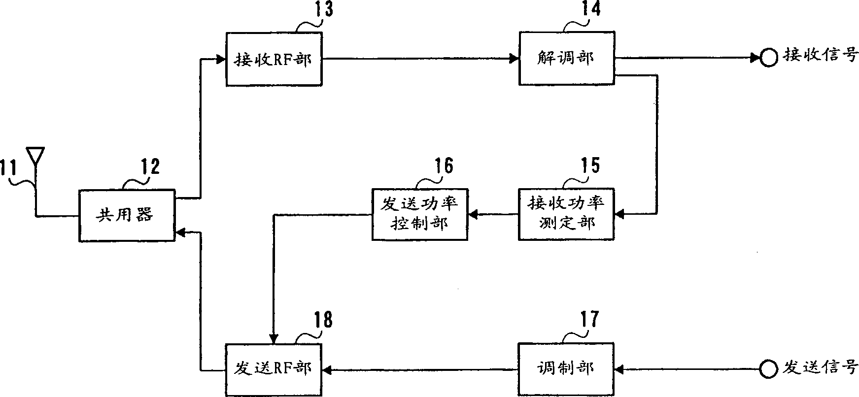
[0036] The duplexer 202 switches the signal path between transmission and reception, outputs the signal received from the antenna 201 to the reception RF unit 203 , and outputs the transmission signal output from the transmission RF unit 213 to the antenna 201 .

[0037] The receiving RF unit 203 amplifies the received power, converts the frequency of the received signal, and outputs a baseband signal. The dedicated channel demodulator 204 despreads and demodulates the baseband signal using the dedicated channel spreading code, and extracts the signal of the dedicated channel of the own station. The common channel demodulation unit 205 despreads the baseband signal using the common channel spreading code.

[0038] The first received power measurement unit 206 measures the received power RMD(t1) of the despread dedicated channel. The second received power measurement...

Embodiment 2

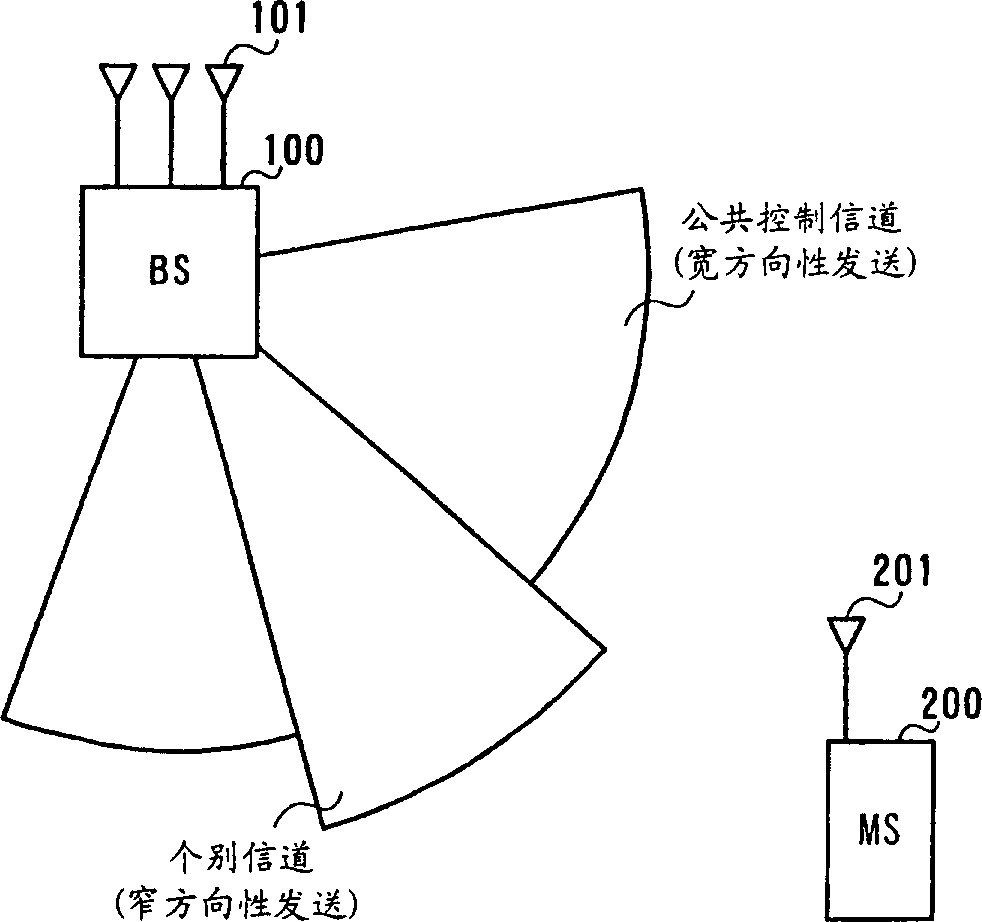
[0063] Embodiment 2 is an embodiment in which the transmission gain is corrected based on the average received power of the common channel and the average received power of the individual channels when the directivity of the individual channels varies.

[0064] Since the structure of the terminal device in Embodiment 2 is the same as figure 2 The same as shown, so its description is omitted.

[0065] When it is determined that there is a directivity deviation, the transmission power control unit 211 increases the gain GM(t2 ) is set to a value obtained by subtracting the difference between the average received power ARMC(t1) of the common channel and the average received power ARMD(t1) of the individual channel from the threshold value C.

[0066] GM(t2)=G0-RMD(t1)-(C-(ARMC(t1)-ARMD(t1))) (7)

[0067] Below, use Figure 5 The flow chart shown is for explaining the flow of transmission power control of the terminal device in the second embodiment.

[0068] First, in the fi...

Embodiment 3

[0074] Embodiment 3 is an embodiment in which the transmission gain is calculated from the received power of the common channel when the directivity of individual channels varies.

[0075] Since the structure of the terminal device in Embodiment 3 is the same as figure 2 The same as shown, so its description is omitted.

[0076] When it is determined that there is a directivity deviation, the transmission power control unit 211 uses the fixed gain G0 and the measured received power RMC(t1) of the common channel to perform Formula to control the gain GM (t2) of the sending amplifier.

[0077] GM(t2)=G0-RMC(t1) (8)

[0078] Below, use Image 6 The flow chart shown is for explaining the flow of transmission power control of the terminal device in the third embodiment.

[0079] First, in the first received power measuring section 206, the received power of the despread dedicated channel of the own station is measured (ST501), and in the same way, in the second received power ...


PUM


Abstract

A first reception power measuring section 206 measures reception power of individual channel signals transmitted with a narrow directivity, and a second reception power measuring section 207 measures reception power of common channel signals transmitted with a wide directivity. A determining section 210 determines the presence or absence of a directional shift based on an average reception power of the individual channel signals and an average reception power of the common channel signals. A transmission power controlling means 211 performs transmission power control based on the determination result. This makes it possible to correctly determine the cause of a reduction in reception power and to control transmission power accurately.

Description

technical field [0001] The present invention relates to a wireless communication terminal device and a transmission power control method in wireless communication systems such as mobile phones and automobile phones. Background technique [0002] In recent years, in order to perform good communication in wireless communication systems such as mobile phones and automobile phones that are spreading rapidly, it is necessary to carefully control transmission power in base station devices and wireless communication terminal devices (hereinafter referred to as "terminal devices"). [0003] Hereinafter, the operation of a conventional terminal device will be described using the drawings. figure 1 It is a structural block diagram of a conventional wireless communication terminal device. [0004] The signal received by the antenna 11 is input to the receiving RF unit 13 via the duplexer 12, and the receiving RF unit 13 amplifies the power of the received signal, converts the frequenc...

Claims


Application Information

Patent Timeline
Patent Type & Authority Applications(China)
IPC IPC(8): H04B7/26H04B7/005H04B7/04
CPCH04W52/10H04B7/0408Y02B60/50H04W52/42H04W52/243
Inventor 平松胜彦宫和行
Owner PANASONIC CORP
Why Eureka
Try Eureka