

Improvement for backlight module support
A backlight module and support technology, applied in optics, nonlinear optics, instruments, etc., can solve the problems of board sagging and high assembly costs
Inactive Publication Date: 2006-11-15
AU OPTRONICS CORP
View PDF0 Cites 1 Cited by
- Summary
- Abstract
- Description
- Claims
- Application Information
AI Technical Summary
Problems solved by technology
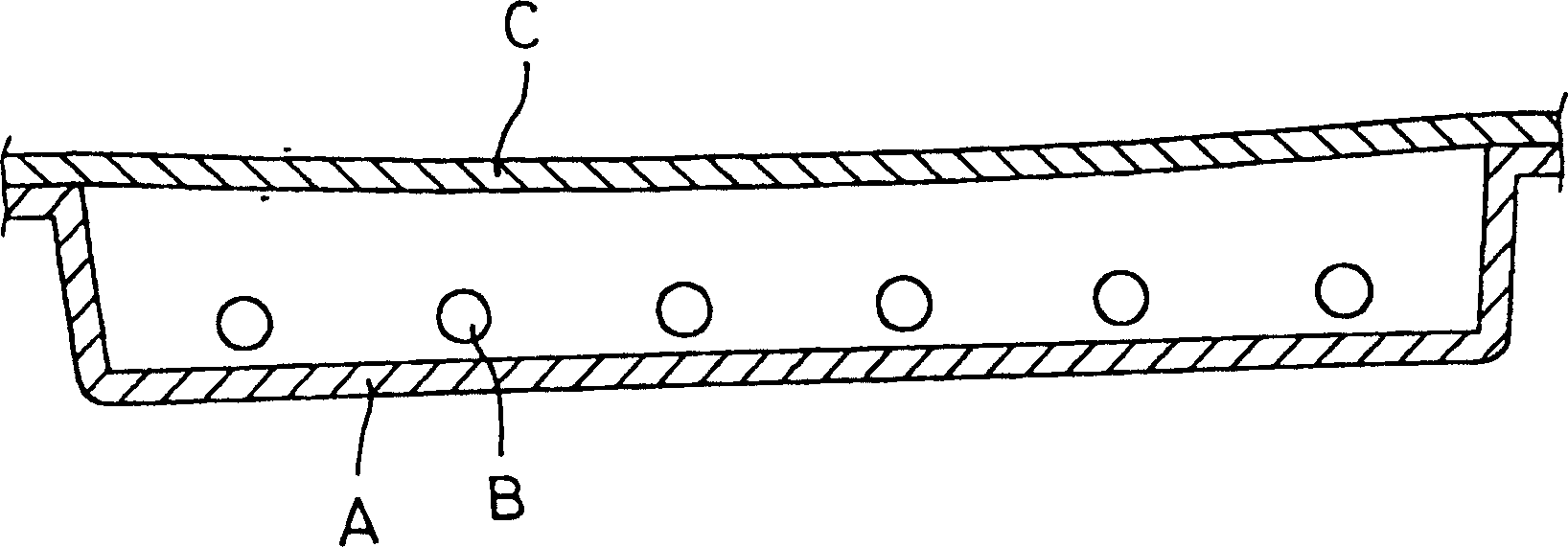
[0003] The existing structure is as figure 1 As shown, the lamp tube B can be fixed inside the lamp housing A, and the diffuser plate C is on the top. In this way, there is no support between the diffuser plate C and the bottom of the lamp housing A. Therefore, due to the material of the diffuser plate itself The impact of weight and ambient temperature and humidity will cause the board to sag toward the center
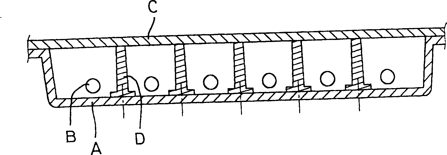
[0004] And as figure 2 As shown, there are several support pieces D vertically installed on the bottom of the lamp housing A, and the support pieces D can touch the diffusion plate C. In addition to the high cost of assembly, in the case of multiple installations, the uniformity of the height or the length of the protrusions becomes another problem. Therefore, how to obtain a flat diffuser plate is a major issue for the backlight module.
Method used
View moreImage
Smart ImageViewing Examples

Examples
Embodiment
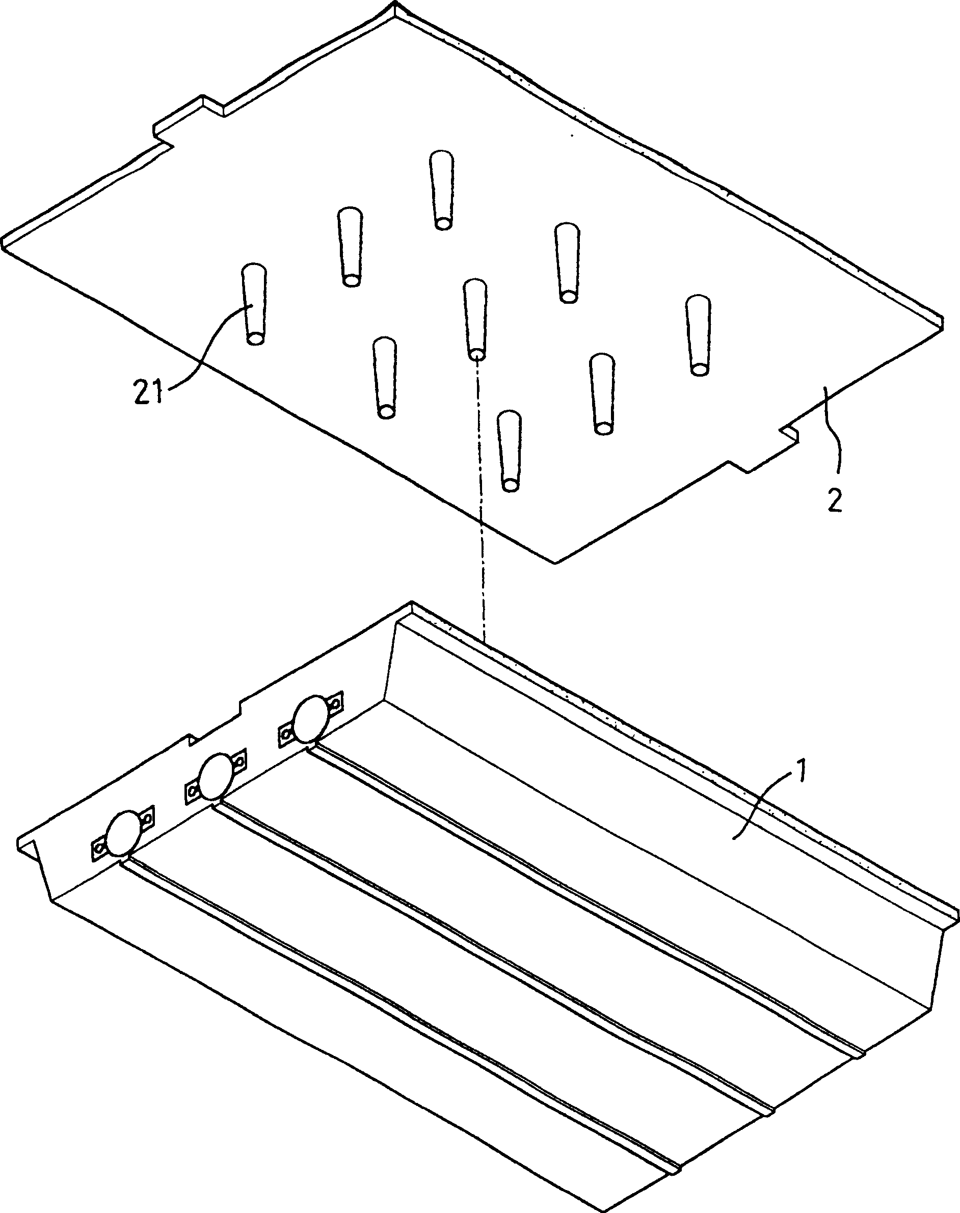
[0019] Please refer to the accompanying drawings again, the present invention is as follows after being assembled Figure 4 As shown, since the diffuser plate 2 itself is supported and abutted by the support member 21, it can be always flat and free from deformation.
[0020] Therefore, through the implementation of the present invention, the diffusion plate 2 can be well supported to prevent deformation without any process, which can be regarded as a major breakthrough of the backlight module.
Login to View More PUM
 Abstract
The present invention is an improvement of the support of the backlight module. It is integrally formed with several protruding supports on the surface of the diffusion plate facing the lamp housing. The protruding length of the supports corresponds to the distance between the bottom of the lamp housing and the diffusion plate. distance, so that after the diffusion plate is covered with the lamp housing, each of the support members can touch the bottom of the lamp housing.
Description
technical field [0001] The present invention is an improvement of the support of the backlight module, especially a support that is integrally formed on the other side of the diffuser plate so that it can be supported against the lampshade. Through the implementation of the present invention, cost can be saved and effective support. Background technique [0002] According to the backlight module is an essential component in the display device, usually it can fix the lamp tube inside the lampshade or lamp housing, and the open end of the lamp shade or lamp housing is connected with a diffuser plate. [0003] The existing structure is as figure 1 As shown, the lamp tube B can be fixed inside the lamp housing A, and the diffuser plate C is on the top. In this way, there is no support between the diffuser plate C and the bottom of the lamp housing A. Therefore, due to the material of the diffuser plate itself The impact of weight and ambient temperature and humidity will cause...
Claims
Login to View More Application Information
Patent Timeline
 Patent Type & AuthorityPatents(China)
IPC IPC(8): G02F1/13357G02F1/1335
Inventor吴志刚
OwnerAU OPTRONICS CORP