Vehicle fuel pressure Linkage braking apparatus

A braking device and oil pressure technology, applied in the field of vehicle braking device, can solve problems such as time-consuming, and achieve the effect of enhancing safety and improving life support

Inactive Publication Date: 2006-11-22
KYMCO
View PDF0 Cites 0 Cited by
  • Summary
  • Abstract
  • Description
  • Claims
  • Application Information

AI Technical Summary

Problems solved by technology

[0008] However, in the front and rear dual-disc brake system 1, manufacturers often use the tee pipe 2 between the cylinder 122 of the left handle unit 12 and the first and second rear brake pipes 16, 16', To complete the stopping work of simultaneously linking these hydraulic cylinders 132,141, and because the front brake unit 13 must be formed into two disconnected hydraulic cylinders 131,132 during manufacture, the manufacturing and assembly project not only It is time-consuming, and the original design is often changed to complete the installation procedures. For manufacturers, it is often caught in a dilemma between cost and safety.

Method used


Image

  • Vehicle fuel pressure Linkage braking apparatus
  • Vehicle fuel pressure Linkage braking apparatus
  • Vehicle fuel pressure Linkage braking apparatus

Examples


Embodiment Construction

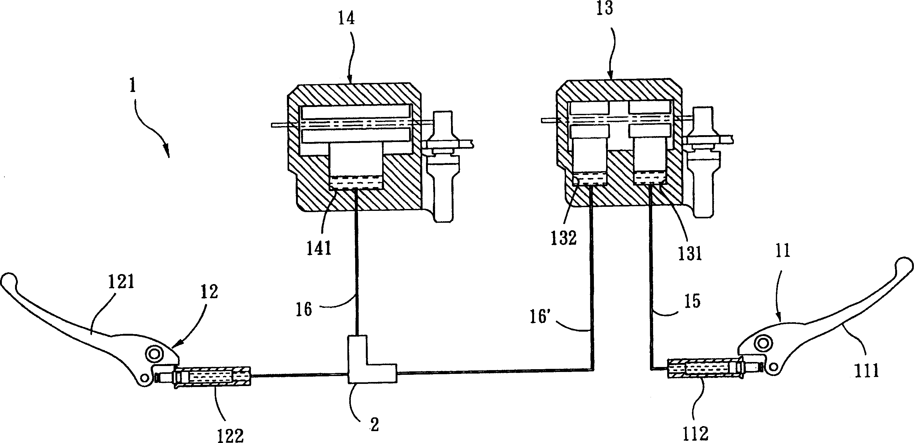
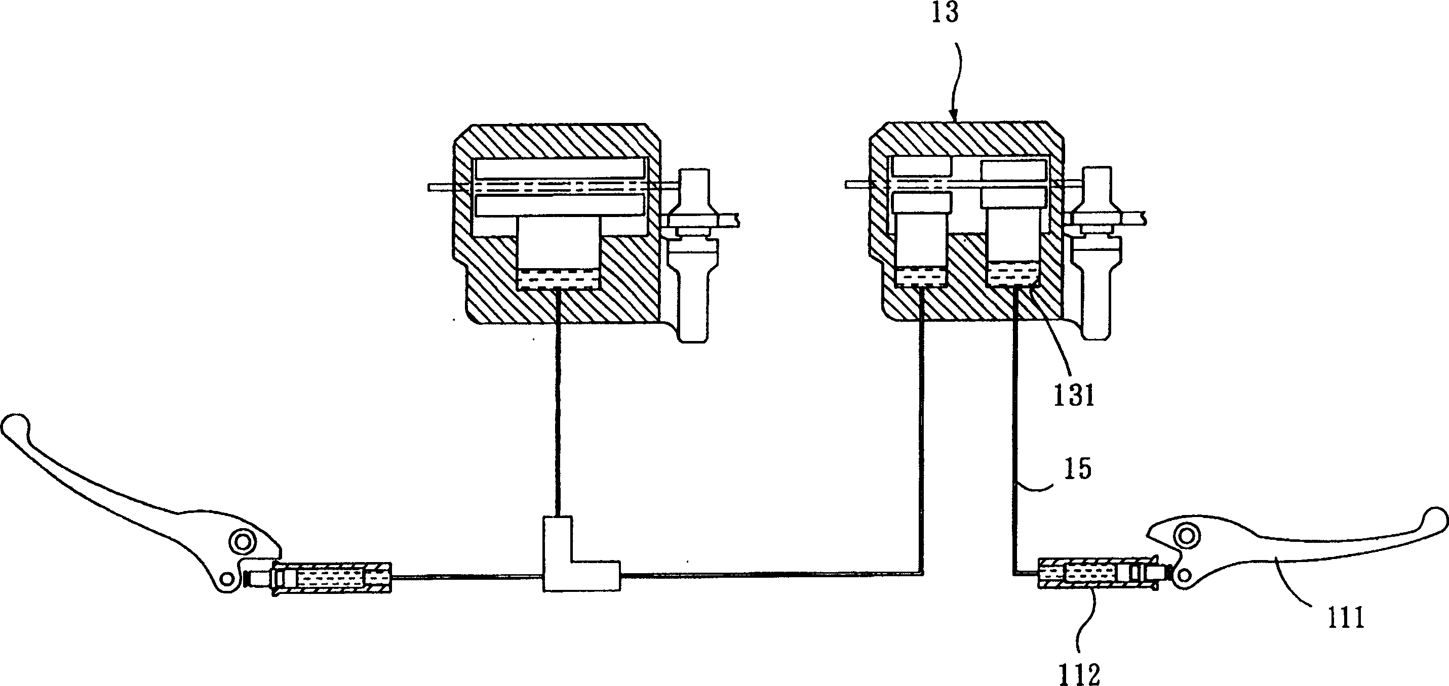
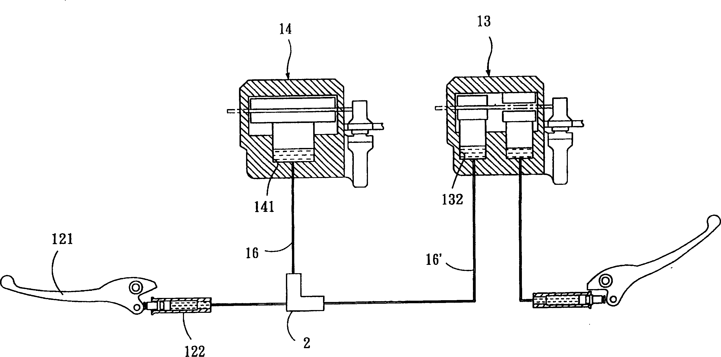
[0057] refer to Figure 4 , the preferred embodiment of the vehicle hydraulic interlocking braking device 3 of the present invention is suitable for a front and rear wheel (for ease of description, not drawn in the figure) of a motorcycle. The vehicle hydraulic linkage braking device 3 includes a first control unit 31, a second control unit 32, a hydraulic cylinder 33, a first hydraulic pipeline 34, a second hydraulic pipeline 35, a The front wheel is connected with a front brake unit 36 ​​to stop the front wheel, and a rear brake unit 37 is connected with the rear wheel to stop the rear wheel.

[0058] The first control unit 31 has a right handle 311 and a cylinder 312 adjacent to each other. The second control unit 32 has a left handle 321 and a cylinder 322 adjacent to each other.

[0059] The hydraulic cylinder 33 has a body 331, a first through groove 333 defined by the first inner wall surface 332 of the body 331, and a second through groove defined by the second inner...


PUM


Abstract

A vehicle hydraulic interlocking braking device, comprising: a hydraulic cylinder, including a body, a first and a second through groove defined by an inner wall of the body and not communicating with each other, and a through groove extending through the first 1. The connecting rod in the two through grooves, and most of the elastic parts respectively pushed between the connecting rod and the inner wall surface; a first control unit with a right handle and an actuator; a second control unit with Left handle and actuating cylinder; there are first oil pressure pipelines in the front and rear sections, the front section and the rear section communicate with the first through groove respectively, and the front section is connected to the actuating cylinder and the first control unit The first through groove; at least one front brake unit connected with the rear section; a second hydraulic pipeline with front and rear sections, the front section and the rear section communicate with the second through groove respectively, the front section It communicates with the cylinder of the second control unit and the second channel; at least one rear brake unit connected with the rear section. The invention is easy to install and has high safety.

Description

【Technical field】 [0001] The present invention relates to a vehicle braking device, in particular to a vehicle oil pressure interlocking braking device installed in a vehicle with front and rear double disc brake systems. 【Background technique】 [0002] At present, the common vehicle brake systems on the market can be divided into three types: front and rear double drums, front disc and rear drums, and front and rear double discs. Among them, the front and rear dual disc brakes have the best stopping efficiency. refer to figure 1 , the front and rear double-disc brake system 1 is used to brake the front and rear wheels (not shown) of a motorcycle, and has a right handle unit 11, a left handle unit 12, a front brake unit 13, a rear The brake unit 14, a front brake pipeline 15, a first rear brake pipeline 16, and a second rear brake pipeline 16'. [0003] The right handle unit 11 includes a right handle 111 and a cylinder 112 , and the left handle unit 12 includes a left han...

Claims


Application Information

Patent Timeline
Patent Type & Authority Patents(China)
IPC IPC(8): B60T8/26B62L3/08
Inventor 董锟男
Owner KYMCO
Why Eureka
Try Eureka