Handle for switch and switch using it

A handle and switch technology, applied in the direction of electrical switches, electrical components, circuits, etc., can solve the problems of cheap, difficult to obtain a sense of luxury, difficult to obtain a sense of luxury, and achieve the effect of preventing damage to the appearance

Inactive Publication Date: 2007-01-03
MATSUSHITA ELECTRIC WORKS LTD
View PDF4 Cites 0 Cited by
  • Summary
  • Abstract
  • Description
  • Claims
  • Application Information

AI Technical Summary

Problems solved by technology

[0036] But when Figure 88 ~ Figure 92 In the shown key handle 2, it is necessary to use the above-mentioned molding materials containing coloring materials, and the materials used are limited. In order to ensure the color quality of the decorative line 33a and reduce the color quality caused by the decorative line 33a on each material used, The surface is rough, and there is a problem that the irradiation conditions of the laser beam need to be changed, which increases the cost, and it is difficult to obtain a sense of luxury, and the problem is that it is cheap compared with the above-mentioned key handle 2
Moreover, it is difficult to obtain a sense of luxury by setting the above-mentioned line board on the front side of the operating handle.

Method used


Image

  • Handle for switch and switch using it
  • Handle for switch and switch using it
  • Handle for switch and switch using it

Examples


Embodiment 1

[0155] Refer below Figure 1 to Figure 14 The key grip 2 of this embodiment will be described.

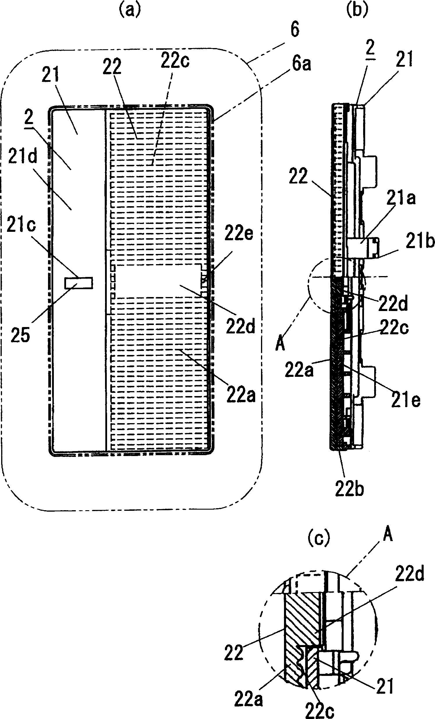
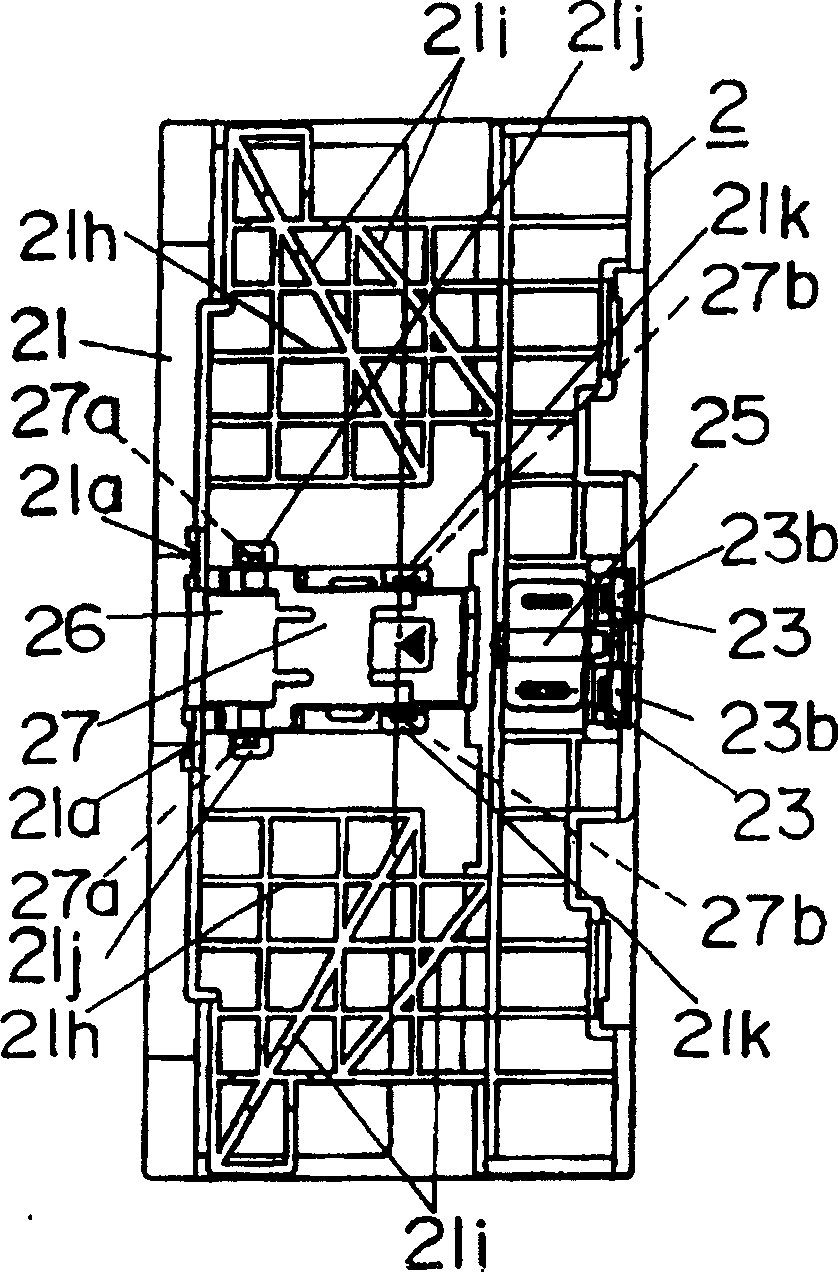
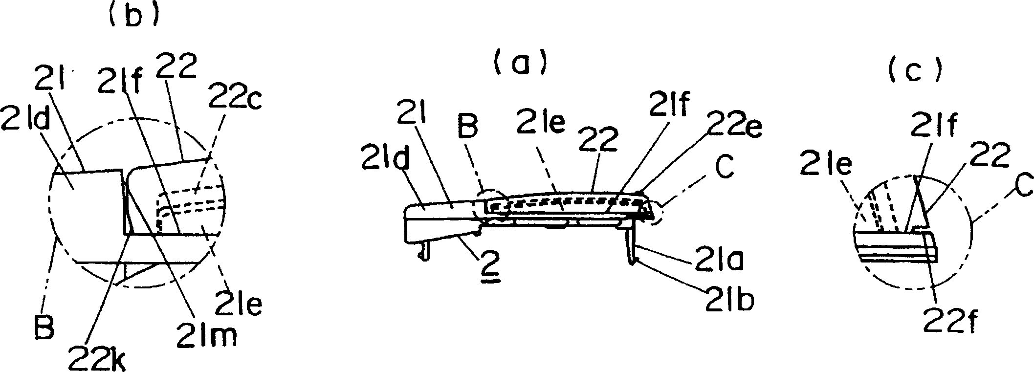
[0156] The key handle 2 of the present embodiment is a key handle 2 used, as Figure 1 to Figure 5 As shown, there is a handle body 21 composed of a molded product of synthetic resin (such as ABS resin, etc.) whose outer peripheral shape is formed into a rectangular shape, and a molded product of transparent synthetic resin (such as acrylic resin, etc.) that is adhered to the handle body. The handle cover 22 of the front side of 21. The following is the same as the previous example, and will be arranged on the above-mentioned 3 installation frames 4 (refer to Figure 8 , Figure 9 , Figure 81 ) in the window 4a, the direction along the longitudinal direction of the window 4a will be described as the up-down direction of the key grip 2.

[0157] The handle cover 22 is adhered to the front side of the handle body 21 in the form of aligning up and down on the handle body 21, and...

Embodiment 2

[0178] The basic structure of the key handle 2 of the present embodiment is substantially the same as that of Embodiment 1, as Figure 19 to Figure 23 As shown, there is a handle body 21 (see Figure 24 ) and the handle cover 22 attached to the front side of the handle body 21 (refer to Figure 25 and Figure 26 ) is a key handle for 2 that is formed to block the opening hole 6a of the decorative plate 6 with two key handles. About one-half of the formations differ at this point. That is, the outer peripheral shape of the key handle 2 of the present embodiment is formed into the same shape as the two key handles 2 described in the previous structure, and the respective vertical dimensions of the handle body 21 and the handle cover 22 are in accordance with the actual The handle main body 21 and the handle cover 22 in Example 1 are formed to approximately half the size in the vertical direction. and, Figure 26 A part with a dotted oblique line in the middle indicates a pa...

Embodiment 3

[0180] The basic structure of the key handle 2 of the present embodiment is substantially the same as that of Embodiment 1, as Figure 27 to Figure 31 As shown, there is a handle body 21 (see Figure 32 ) and the handle cover 22 attached to the front side of the handle body 21 (refer to Figure 33 and Figure 34 ) is a key handle for 3 that is formed to block the opening hole 6a of the decorative plate 6 with 3 key handles. A third of the formations differ on this point. That is, the outer peripheral shape of the key handle 2 of this embodiment is formed to be the same shape as the three key handles 2 described in the previous structure, and the respective vertical dimensions of the handle body 21 and the handle cover 22 are based on the dimensions of the embodiment. 1, the size of the handle body 21 and the handle cover 22 in the vertical direction is one-third of each. and, Figure 34 A part with a dotted oblique line in the middle indicates a part where embossing is pe...


PUM


Abstract

To provide a handle for a switch and the switch, the appearances of which can be improved at low cost. A piano handle 2 comprises a handle body 21 molded of synthetic resin, and a handle cover 22 molded of transparent synthetic resin that covers the front side of the handle body 21. A decorative pattern 22c is formed in the handle cover 22 itself on the back of the handle cover 22. Since the decorative pattern 22c is made in the area except a card cover part 22d on the back of the handle cover 22 and is in a corrugated rugged shape formed on the back of the handle cover 22, and the handle cover 22 is molded of transparent synthetic resin, the decorative pattern 22c on the back of the handle cover 22 shows a striped pattern when viewed from the front of the handle cover 22.

Description

technical field [0001] The invention relates to a switch handle and a switch using the handle. Background technique [0002] Conventionally, among various switches, in order to improve the appearance quality and give a sense of luxury, etc., a switch provided with a textured portion on the front (operating surface) of an operating handle (switch handle) is provided. [0003] As an example of a switch in which a pattern portion is provided on the front of the handle, there is provided on the front side of a switch body composed of a push button switch having a pushable button handle, one end is pivotally supported on the switch body, and the rear surface is connected to the button. A key lever switch with a key handle opposite to the handle. The key handle and the key are the same structure that can use one end as a fulcrum to press the other end. Moreover, the operation surface of the key handle of the key handle type switch is larger than that of the button handle, and th...

Claims


Application Information

Patent Timeline
Patent Type & Authority Patents(China)
IPC IPC(8): H01H21/22H01H25/00H01H21/00H01H3/12H01H9/02H01H9/16H01H11/00
Inventor 川本隆司矢野学矢尾和基岛和义
Owner MATSUSHITA ELECTRIC WORKS LTD
Why Eureka
Try Eureka