

Linear compression latch
A straight-line, latching technology, used in building locks, carpet fastening devices, mechanical equipment, etc., can solve problems such as reducing the degree of isolation between the closed body and the environment, and achieve the effect of easy sealing, simple assembly and installation
- Summary
- Abstract
- Description
- Claims
- Application Information
AI Technical Summary
Problems solved by technology
Method used
Image

Examples
Embodiment Construction
[0038] The present invention provides a simple straight line squeeze latch that can be easily and reliably installed on the outside of a door or panel. The straight line squeeze latch of the present invention sets steady preset compression. At the same time, only a small part of the latch mechanism protrudes inside the closure body, making the latch easy to seal against the environment. The linear extrusion latch of the present invention is simple to manufacture, assemble and install, and preferably can be assembled from less than a dozen parts.
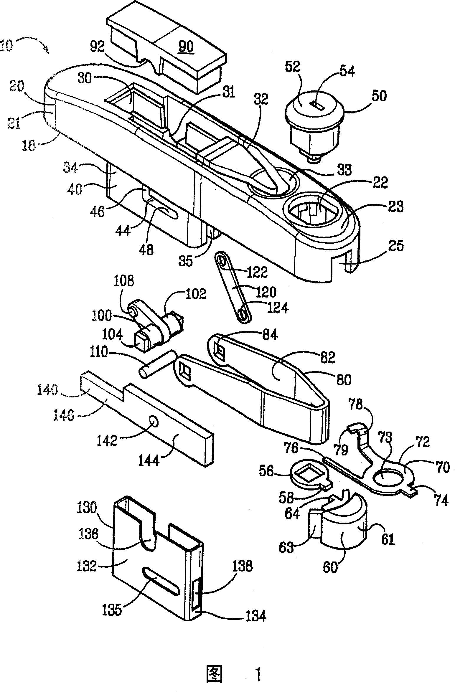
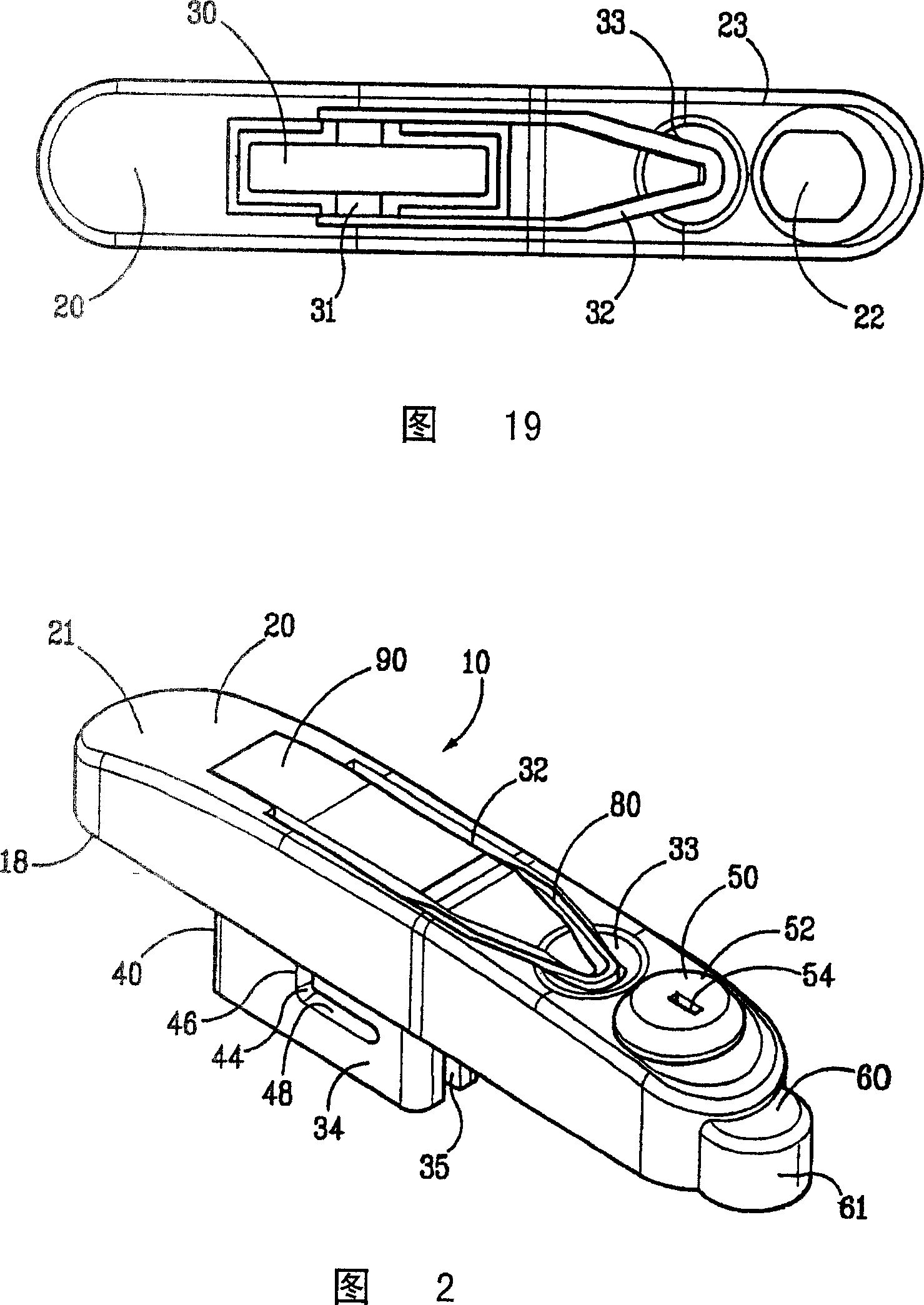
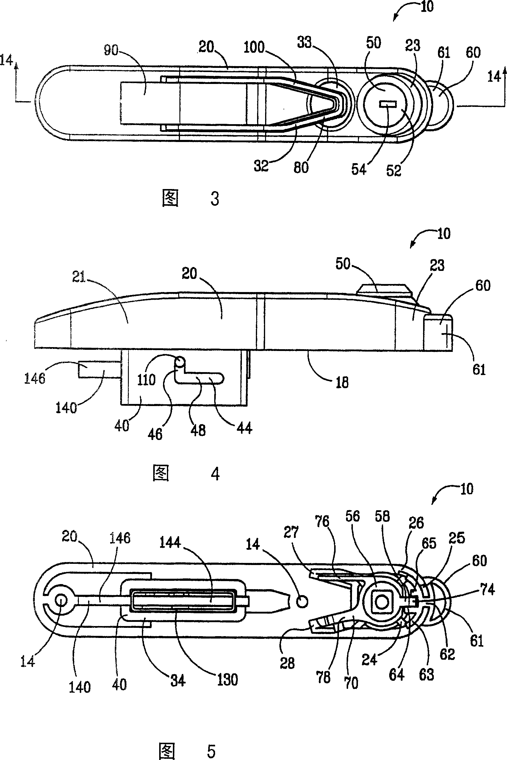
[0039] Referring to the drawings, in which like parts in the various views have like references, FIG. 1 shows an exploded perspective view of a linear squeeze latch 10 according to the present invention.
[0040] The linear squeeze latch 10 includes an elongated housing 20 for mounting on the outside of a door or panel 210 of a cabinet or enclosure 200 having a frame 220 (FIG. 14). Housing 20 includes an upper portion 21 (best seen...
PUM
 Abstract
Description
Claims
Application Information