Narrow gap electric arc spraying gun
An electric arc spraying and narrow gap technology, applied in the field of spraying guns, can solve the problems of increased process, low deposition rate and spraying efficiency, waste of spraying materials, etc., and achieve the effects of saving spraying materials, shortening spraying time and improving work efficiency
- Summary
- Abstract
- Description
- Claims
- Application Information
AI Technical Summary
Problems solved by technology
Method used
Image
Examples
specific Embodiment approach 1
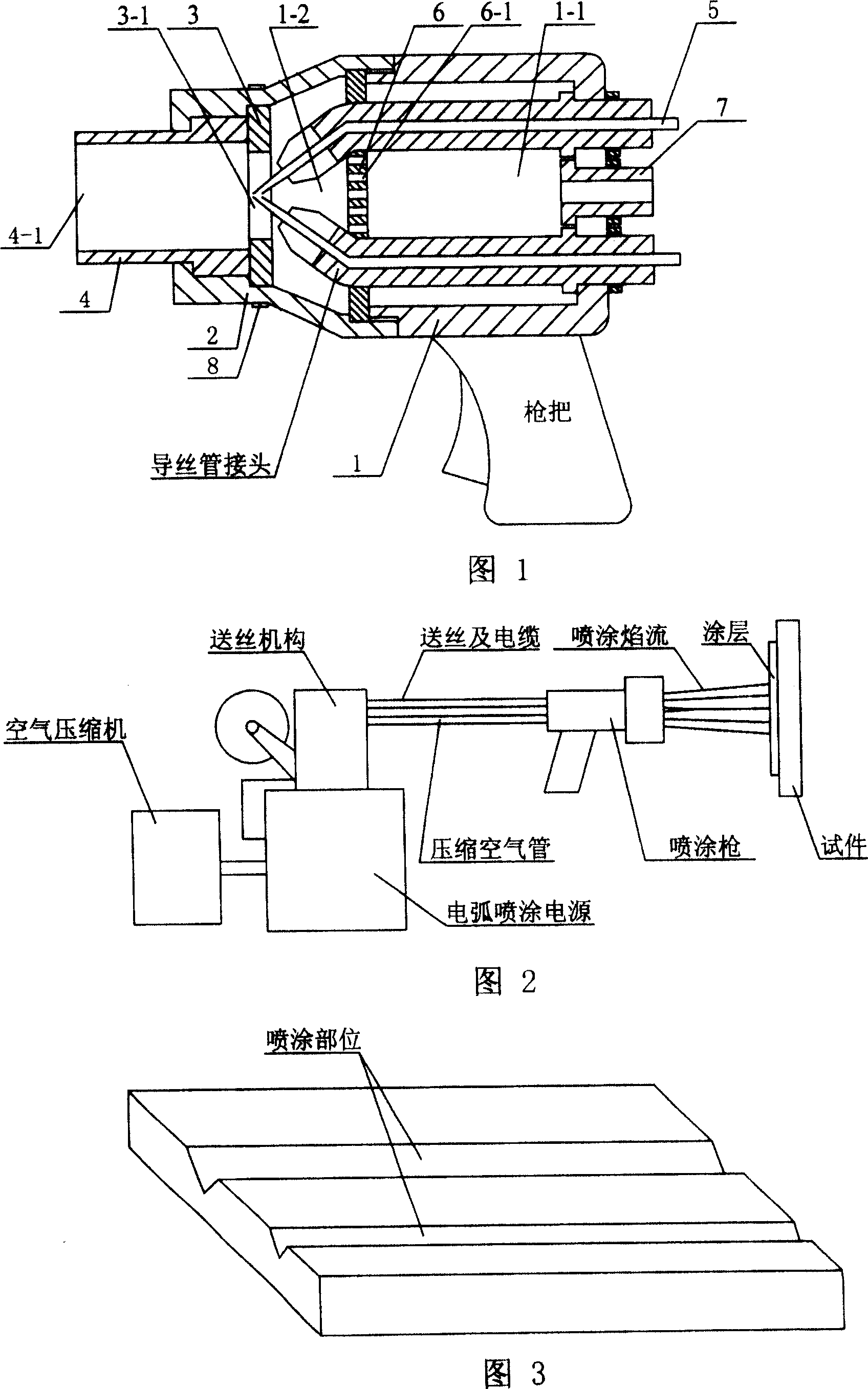
[0006] Embodiment 1: The design guiding idea of the narrow-gap arc spray gun of the present invention is to ensure that the spraying flame is rectangular, so that the spraying effect of the narrow gap can be achieved, so the key technology is the innovation of the nozzle structure of the spraying gun. It includes a gun body 1, a spraying wire 5 arranged in the gun body 1, a gun nozzle fixing piece 2 is arranged at the front end of the gun body 1, and a rectangular airflow hood 3 is fixed inside the gun nozzle fixing piece 2. The rectangular airflow hood 3 A rectangular through hole 3-1 is arranged at the center of the hood, the end of the spraying wire 5 is arranged at the position of the through hole 3-1, and a rectangular ceramic nozzle 4 is arranged in front of the rectangular airflow hood 3. The rectangular ceramic nozzle The center of 4 is provided with a rectangular through hole 4-1, the aforementioned rectangular ceramic nozzle 4 is clamped with the gun nozzle fixing m...
specific Embodiment approach 2
[0009] Specific embodiment 2: This embodiment is the process in which the applicant uses the spray gun of the present invention to repair the piston ring groove on the train piston: 1. Conditions: The piston ring groove on the train piston is on both sides of the groove during use. It is often scrapped due to severe wear and tear. The material is cast steel, and wear occurs on both sides of the groove. One side of the groove is seriously worn, and the wear amount is 0.5mm. Both sides of the groove need to be restored to size. 2. Spraying method: first, degreasing and decontamination of the spraying part of the piston ring groove, rough machining the piston ring groove, then roughening by sandblasting, and installing the piston on the rotary table, according to the process described in Embodiment 1 Connect the equipment, adjust the various process parameters required for spraying, and start spraying after everything is ready. During the spraying process, the pressure of the comp...
specific Embodiment approach 3
[0010] Specific embodiment three: This embodiment is the process of using the spray gun of the present invention to spray the components on the chemical equipment: 1. Conditions: The sprayed components are shown in Figure 3, and the material is ductile iron, which is a new product and requires a slideway The surface is sprayed with wear-resistant material to improve the service life. 2. Spraying process: First, deoil and decontaminate the sprayed parts on the surface of the slideway, then sandblast and roughen, place the workpiece on the workbench, connect the equipment according to the process in the previous embodiment, and adjust the various items required for spraying. The process parameters are ready to start spraying: the pressure of the compressed air is 0.8Mpa, the gas flow of the compressed air is adjusted to the state of the minimum spraying arc flame flow, the spraying voltage is 32V, and the spraying current is 120A. The spraying angle is 90°, the distance between ...
PUM
 Abstract
Description
Claims
Application Information
 - R&D
- Intellectual Property
- Life Sciences
- Materials
- Tech Scout
- Unparalleled Data Quality
- Higher Quality Content
- 60% Fewer Hallucinations
Browse by: Latest US Patents, China's latest patents, Technical Efficacy Thesaurus, Application Domain, Technology Topic, Popular Technical Reports.
© 2025 PatSnap. All rights reserved.Legal|Privacy policy|Modern Slavery Act Transparency Statement|Sitemap|About US| Contact US: help@patsnap.com

