Middle-temp phase-change energy-accumulating heating appliance

A phase-change energy storage and heater technology, applied in the field of heaters, can solve problems such as large peak-to-valley difference of power supply network and environmental pollution, and achieve the effects of solving the peak-to-valley difference of power supply network, convenient use and reasonable design.

Inactive Publication Date: 2002-02-06
TSINGHUA UNIV
View PDF0 Cites 1 Cited by
  • Summary
  • Abstract
  • Description
  • Claims
  • Application Information

AI Technical Summary

Problems solved by technology

[0003] The purpose of the invention is to solve the problems of environmental pollution and excessive peak-to-valley difference of the power supply network, make up for the deficiencies of the prior art, and provide a medium-temperature phase-change energy storage heater

Method used


Image

  • Middle-temp phase-change energy-accumulating heating appliance
  • Middle-temp phase-change energy-accumulating heating appliance
  • Middle-temp phase-change energy-accumulating heating appliance

Examples


Embodiment Construction

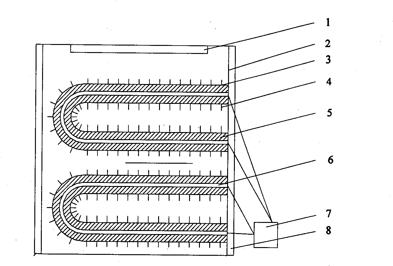
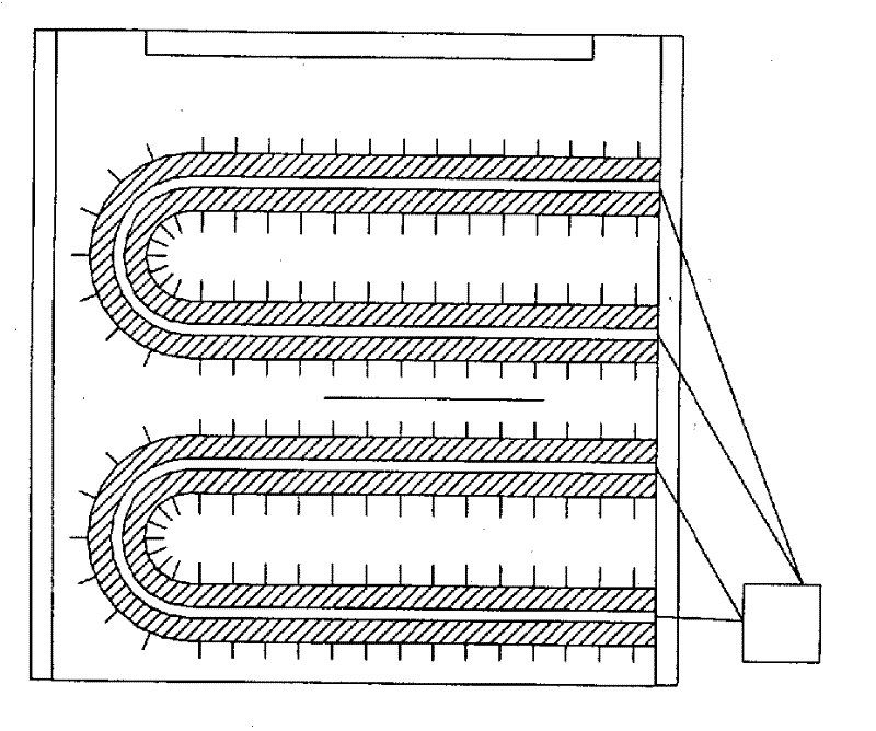
[0011] The embodiment structure of a medium temperature phase change energy storage heater designed in the present invention is as follows figure 1 , 2 As shown, the detailed description is as follows in conjunction with the drawings:

[0012] This embodiment includes the following components: air door 1, outer cover 2, U-shaped tube 3, enhanced heat exchange fins 4, phase change material 5, temperature control heating device 6, time controller 7, and thermal insulation layer 8.

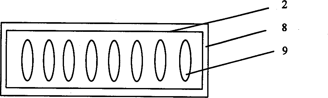
[0013] The connection relationship of the components: the front, rear, left, and right sides of the outer cover 2 are all closed metal surfaces, and an insulation layer 8 is arranged outside; the bottom surface is exposed, and the upper surface has a heat dissipation hole 9, and the damper 1 is installed at the heat dissipation hole of the outer cover 2. Two U-shaped tubes 3 are fixed in the outer cover 2. The U-shaped tube 3 is made of stainless steel; the outer surface of the U-shaped tube 3 is welded...


PUM


Abstract

A heating appliance is composed of a casing with surficial insulating layer, heat radiating holes and air gate, one or more U-shaped tubes with fins for forcing heat exchange, phase-change material and temp-controlling heater in said U-shaped tube, and time controller connected to said heater. It can generate and accumulate heat energy when electric power network is in valley period and fastly release heat energy when electric power network is in peak period.

Description

Technical field [0001] The invention belongs to the technical field of heaters, and particularly relates to the structural design of energy storage heaters. Background technique [0002] In recent years, environmental pollution has become increasingly serious. In winter, the main pollution in northern cities in my country comes from the emission of dust and harmful gases caused by burning coal for heating. The society urgently needs to introduce new pollution-free or low-polluting heating methods. Therefore, the use of electric heating, such as electric heating oil lamps, electric heating quartz tube heaters, electric heating glass-ceramic radiant heaters, etc. are more and more popular. However, there is a problem of excessive peak-to-valley difference in the power supply network in my country and even the world, which seriously hinders the rational use of electricity and also hinders the effective development of electric heaters. Because most of the time to use this type of hea...

Claims


Application Information

Patent Timeline
Patent Type & Authority Applications(China)
IPC IPC(8): F24D13/04F24D15/02
CPCY02B30/12
Inventor 王智超张寅平狄洪发陈科科罗晓熹曹国光
Owner TSINGHUA UNIV
Why Eureka
Try Eureka