Crankcase structure for engine of motorcycle

A technology for motorized two-wheeled vehicles and crankcases, which is applied to the lubrication of engines, machines/engines, motor vehicles, etc., to achieve the effect of simple structure and improved warm-up operation performance

Inactive Publication Date: 2002-03-06
HONDA MOTOR CO LTD
View PDF1 Cites 3 Cited by
  • Summary
  • Abstract
  • Description
  • Claims
  • Application Information

AI Technical Summary

Problems solved by technology

[0003] However, when the bottom of the crankcase is formed substantially flat along the horizontal plane, the oil groove in the crankcase becomes wide and shallow. In order to effectively draw oil from the oil groove, it is necessary to store more than a certain amount of oil, and complicated installation is necessary to reduce the amount of oil. oil-absorbing structure

Method used


Image

  • Crankcase structure for engine of motorcycle
  • Crankcase structure for engine of motorcycle
  • Crankcase structure for engine of motorcycle

Examples


Embodiment Construction

[0017] Hereinafter, embodiments of the present invention will be described with reference to embodiments of the present invention shown in the drawings.

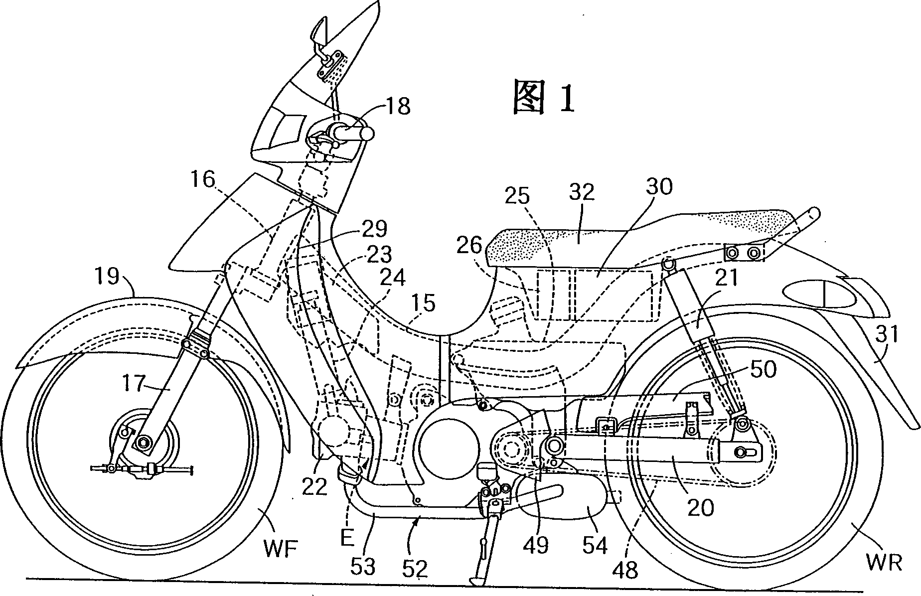
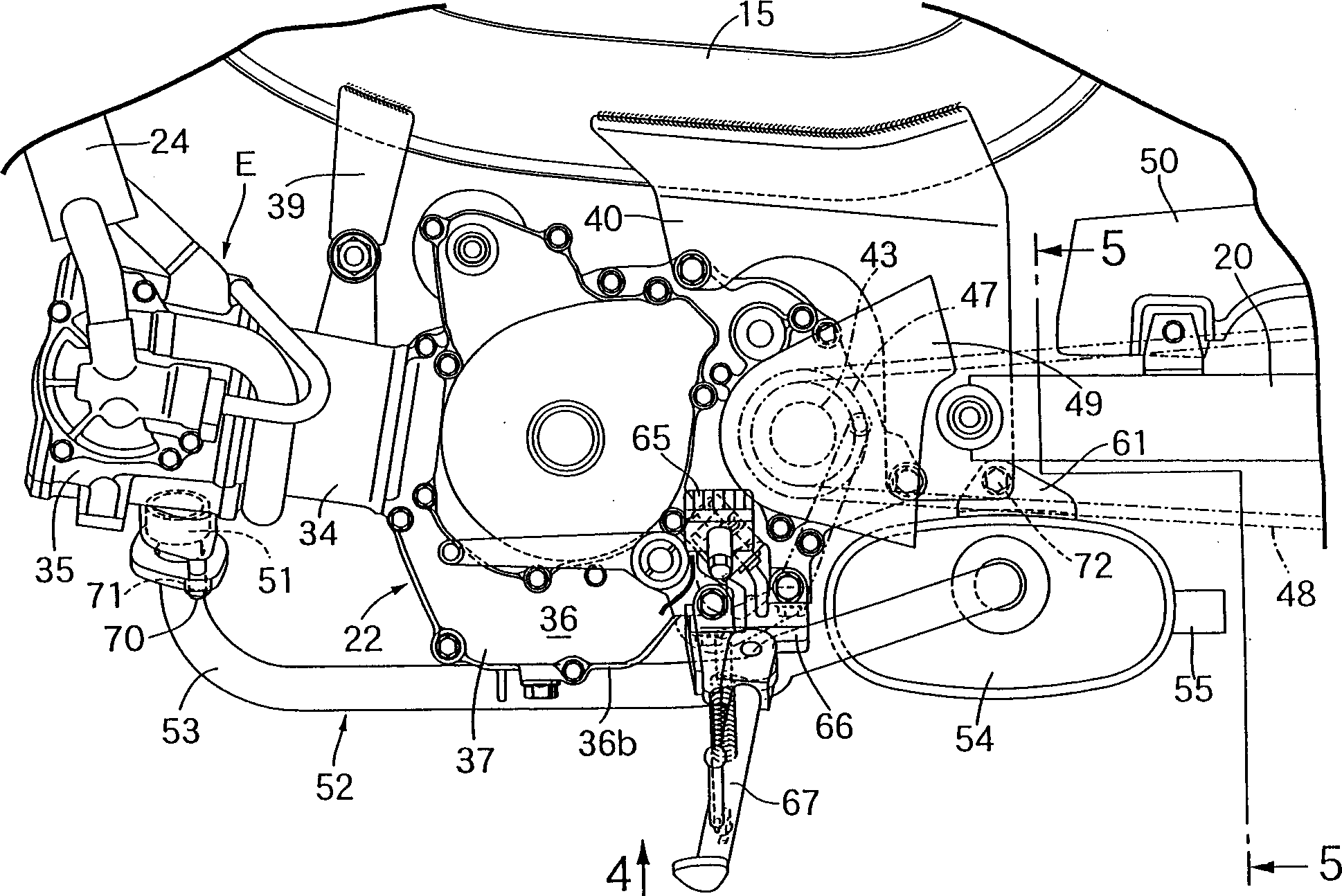
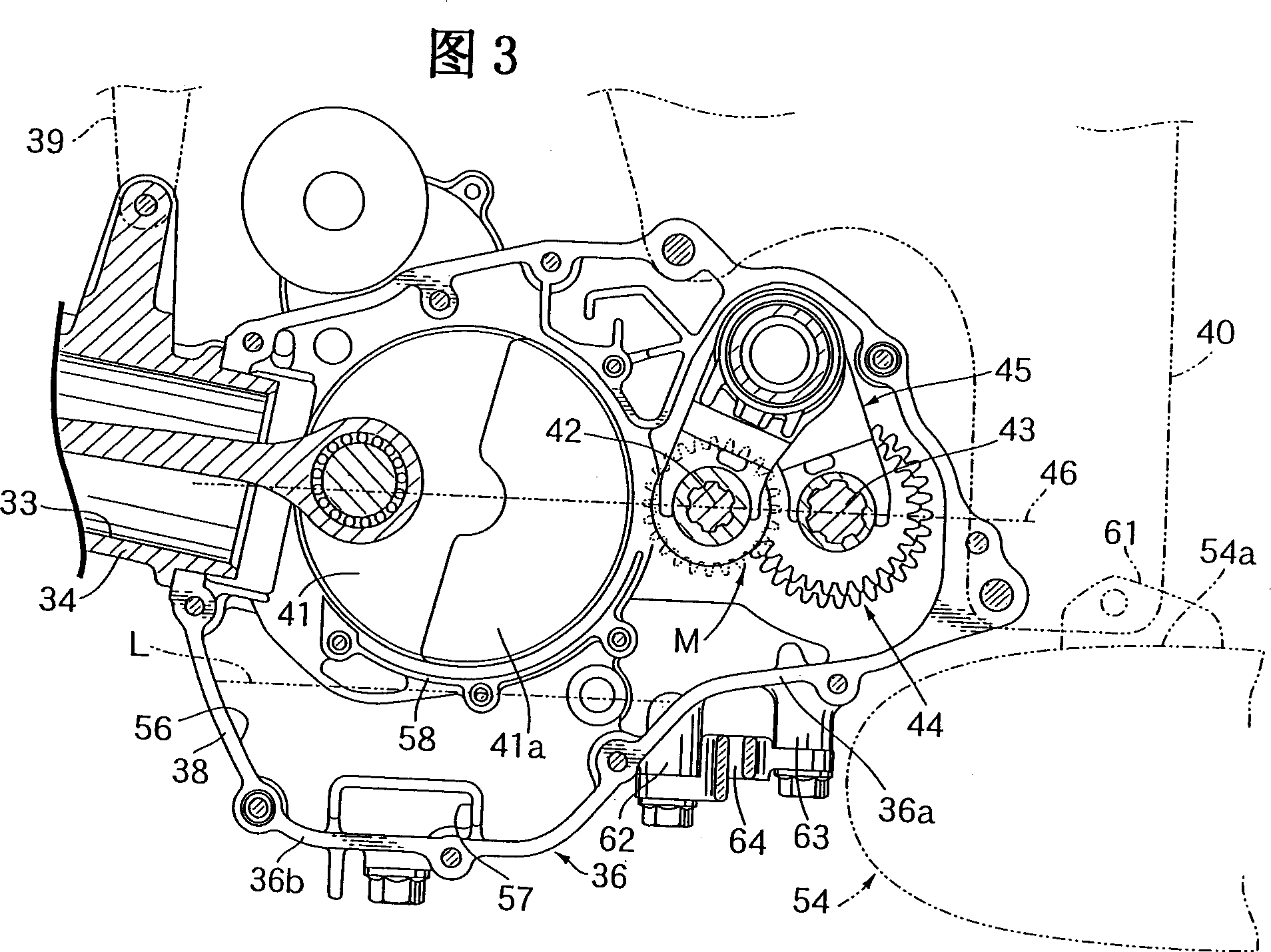
[0018] figure 1- Figure 5 Representing the first embodiment of the present invention, Fig. 1 is a side view of a motorized two-wheeled vehicle, figure 2 It is a partially enlarged view of FIG. 1, FIG. 3 is a longitudinal sectional side view showing the interior of the crankcase, and FIG. 4 is a figure 2 Bottom view of middle arrow 4, Figure 5 is along figure 2 Cross-sectional view of line 5-5.

[0019] First, in FIG. 1, a front fork 17 that supports a front wheel WF is pivotally supported steerably on a head pipe 16 provided on a front end of a frame 15 of a motorcycle. The lever 18 is connected to the upper end of the front fork 17 , and the front fender 19 covering the upper side of the front wheel WF is supported by the front fork 17 . In addition, the rear fork 20 supporting the rear wheel WR is pivotally supporte...


PUM


Abstract

A bottom wall rear part 36a of the crankcase 36 corresponding to the transmission shafts 42 and 43 can secure a space for arranging at least a part of an exhaust muffler 54 under the bottom wall rear part 36a, and is formed higher than a bottom wall front part 36b of the crankcase 36 corresponding to the crankshaft 41. To efficiently pump up oil with a simple pumping-up structure, and to improve warming-up performance while reducing an oil quantity stored in a crankcase in an engine for a motorcycle or a motor-tricycle for rotatably supporting transmission shafts for orthogonally arranging the axis on an almost horizontal straight line extending in the longitudinal direction by passing through the axis of a crankshaft on the rear side more than the crankshaft in the crankcase.

Description

technical field [0001] The present invention relates to an engine of a two-wheeled motor vehicle or an automatic tricycle, in which a transmission shaft is freely rotatably supported further rearward than the crankshaft on a crankcase which freely rotatably supports the crankshaft, and the transmission shaft is The axis is vertically intersected with a substantially horizontal straight line extending forward and backward through the crankshaft axis, and the present invention particularly relates to improvement of the crankcase structure. Background technique [0002] Conventionally, in such an engine, as disclosed in JP-A-9-242543, the bottom of the crankcase is formed substantially flat along a horizontal plane. [0003] However, when the bottom of the crankcase is formed approximately flat along the horizontal plane, the oil groove in the crankcase becomes wide and shallow. In order to effectively draw oil from the oil groove, it is necessary to store more than a certain a...

Claims


Application Information

Patent Timeline
Patent Type & Authority Applications(China)
IPC IPC(8): B62K11/00B62M7/04F01M5/00F01M11/00F02F7/00
Inventor 菊池一纪饭嶌智司久保田良山口正昭柳田贵之
Owner HONDA MOTOR CO LTD
Why Eureka
Try Eureka