Plasma displaying panel and mfg. method thereof

A plasma and display panel technology, which is applied in the direction of alternating current plasma display panel, cold cathode manufacturing, electrode system manufacturing, etc., can solve the problems of reducing output and so on

Inactive Publication Date: 2002-04-10
HITACHI CONSUMER ELECTRONICS CORP
View PDF0 Cites 22 Cited by
  • Summary
  • Abstract
  • Description
  • Claims
  • Application Information

AI Technical Summary

Problems solved by technology

However, this method also has a manufacturing step of the dicing process, which reduces yield due to barriers being damaged during dicing

Method used


Image

  • Plasma displaying panel and mfg. method thereof
  • Plasma displaying panel and mfg. method thereof
  • Plasma displaying panel and mfg. method thereof

Examples


Embodiment Construction

[0019] Hereinafter, the present invention will be described in detail with reference to examples and drawings.

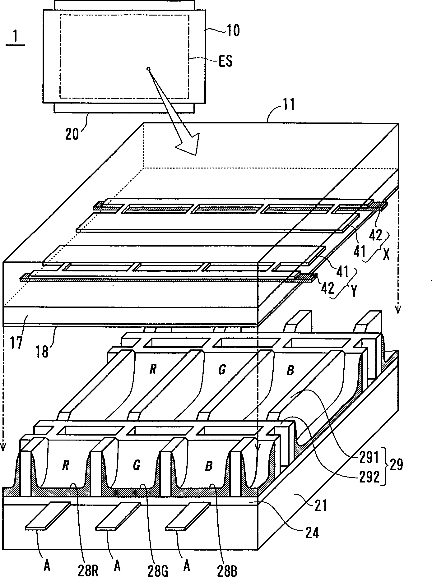
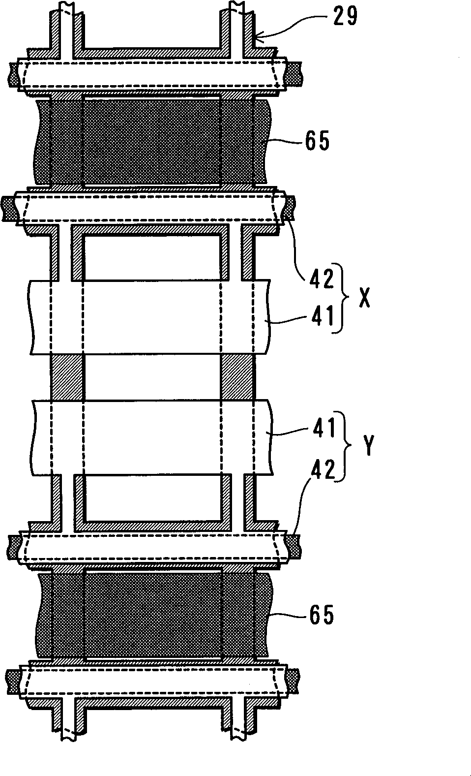
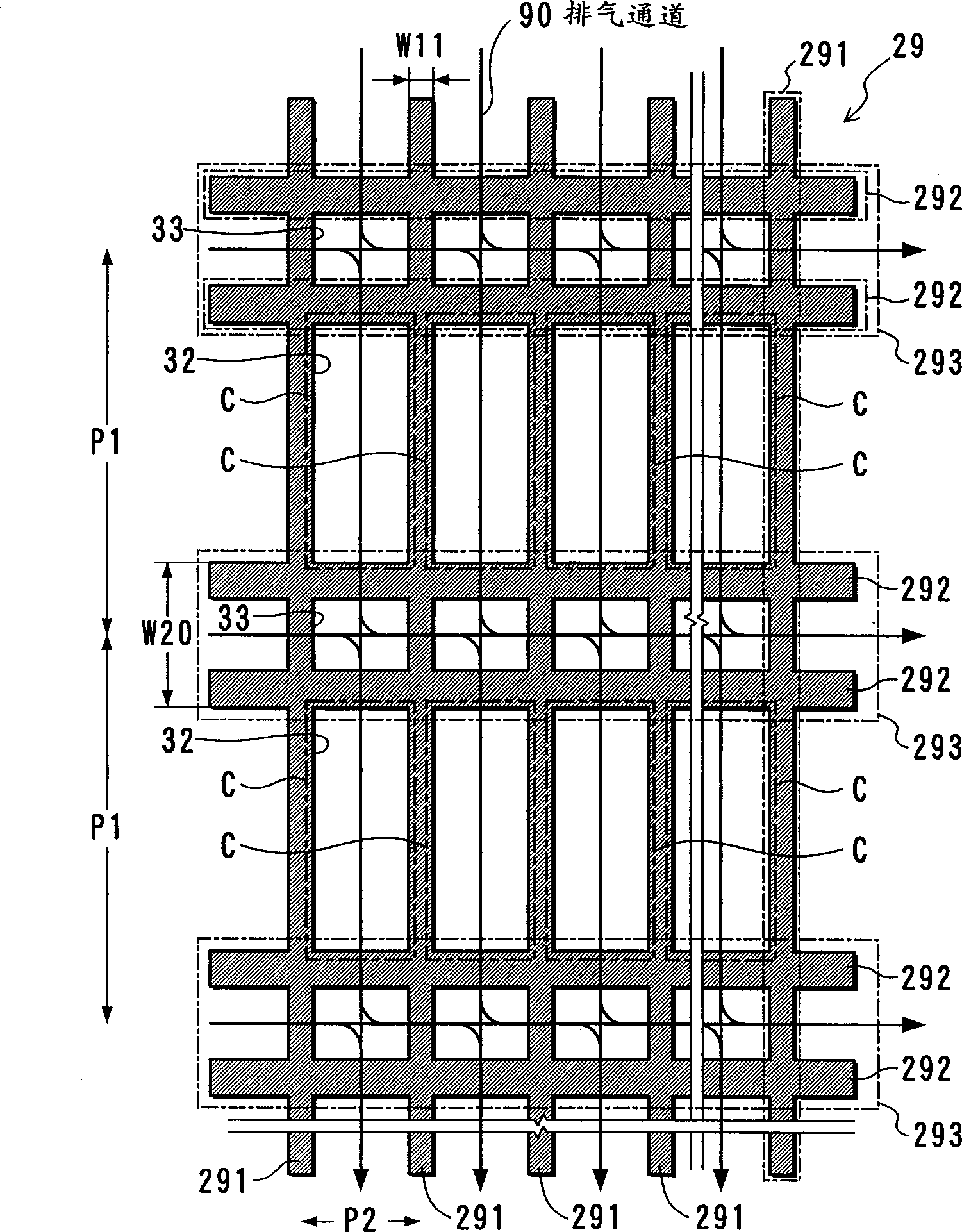
[0020] figure 1 is a schematic diagram of the cell structure of the PDP of the present invention. figure 2 is a plan view showing the arrangement relationship between electrodes and barriers. figure 1 Showing the internal structure, a pair of substrate structures spaced apart from each other are shown.

[0021] The PDP 1 includes a pair of substrate structures (a structure including a substrate on which cell components are arranged) 10, 20, and a display surface ES includes m*n cells. In each cell, the display electrodes X and Y form a pair of electrodes for generating display discharge, the display electrodes extend along the horizontal direction (horizontal direction) of the matrix display, and the address electrodes A extend along the longitudinal direction (vertical direction).

[0022] Display electrodes X, Y are arranged on the inner surface of the glass s...


PUM


Abstract

A plasma display panel (1) is provided that has a good productivity of partition formation and air exhaustion process and realizes a bright and stable display. A discharge gas is filled in a gap between two substrates (10,20). A mesh-patterned partition (29) is arranged on the inner surface of one of the substrates for dividing the gap into plural squares corresponding to a cell arrangement. The partition (29) has low portions (292) for forming a mesh-like air path (90) that travels all gas-filled space enclosed by the partition (29) in a plan view.

Description

technical field [0001] The present invention relates to a plasma display panel (PDP) having a grid pattern, each area of ​​which encloses one or more elements constituting a display surface, and to a method of manufacturing such a PDP. technical background [0002] A commercialized PDP used as a wall-mounted television has a screen size of 60 inches. The PDP is a digital display including binary light emitting cells, so it is suitable for displaying digital data, as a multimedia display. In order to improve the practicality of PDP, a new panel structure is being developed to provide brighter and more stable display, and it can be mass-produced. [0003] An AC type color display PDP uses a surface discharge mode. The electrode distribution of the surface discharge mode is: when displaying discharge, the display electrodes form anodes and cathodes to ensure illumination, and the display electrodes are arranged in parallel on the front substrate or the rear substrate. The ad...

Claims


Application Information

Patent Timeline
Patent Type & Authority Applications(China)
IPC IPC(8): H01J9/02H01J9/24H01J11/14H01J11/22H01J11/34H01J11/36
CPCH01J2211/361H01J9/242H01J11/36H01J11/12
Inventor 国井康彦柴田将之川浪义实山本健一横山敦史矢岛裕介金具慎次若林泰浩藤本晃广南都利之
Owner HITACHI CONSUMER ELECTRONICS CORP
Why Eureka
Try Eureka