
Device for electric connection of two electric apparatuses and electric apparatus adapted for said device

A technology of electrical equipment and electrical connection, which is applied in the direction of conductive connection, electrical component connection, connection, etc., and can solve problems such as impractical cost and long bridge

Inactive Publication Date: 2002-07-24
SCHNEIDER ELECTRIC IND SAS
View PDF0 Cites 9 Cited by
  • Summary
  • Abstract
  • Description
  • Claims
  • Application Information

AI Technical Summary

Problems solved by technology

This results in long, impractical and costly bridges required to make the above connections

Method used


Image

  • Device for electric connection of two electric apparatuses and electric apparatus adapted for said device
  • Device for electric connection of two electric apparatuses and electric apparatus adapted for said device
  • Device for electric connection of two electric apparatuses and electric apparatus adapted for said device

Examples


Embodiment Construction

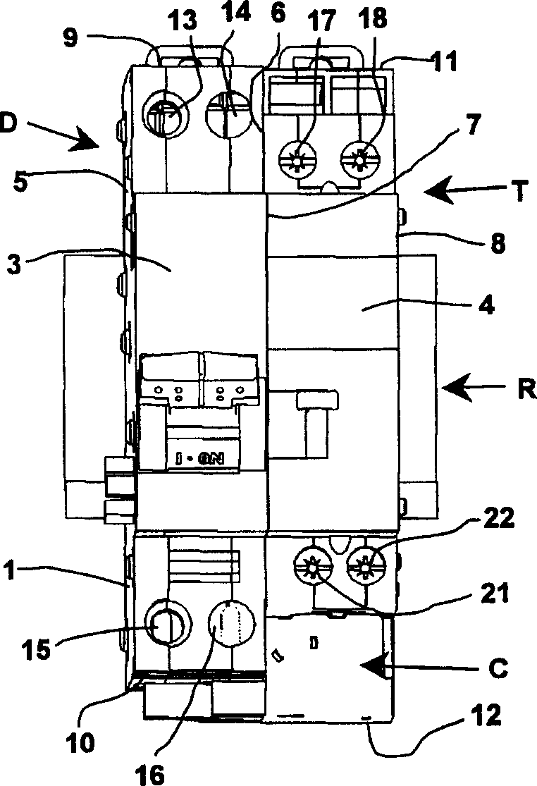
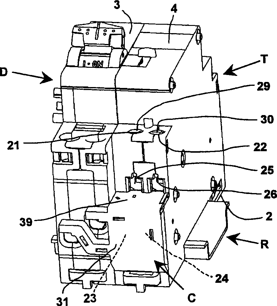
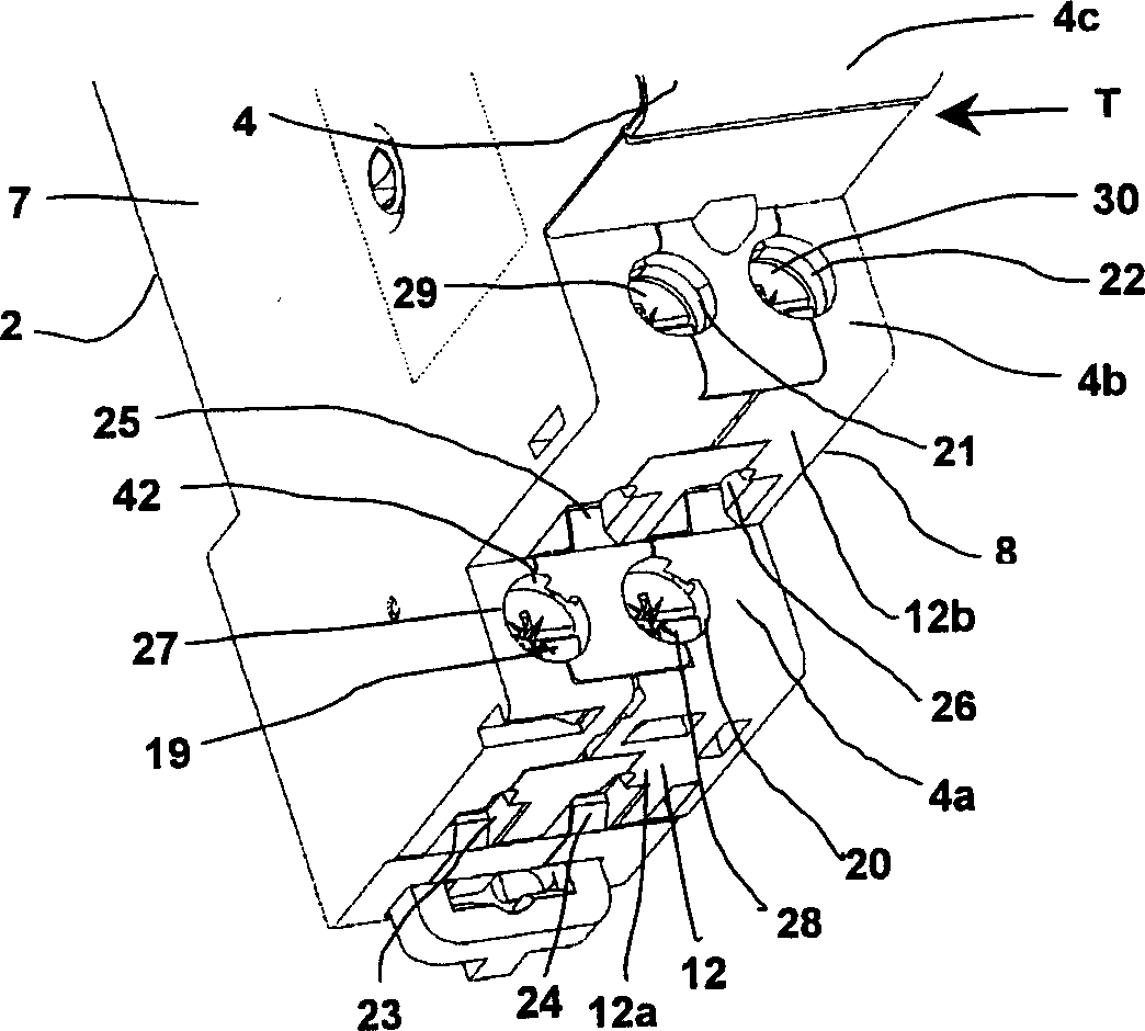
[0016] exist figure 1 and figure 2 , it can be seen that the circuit breaker D and the remote switch T are mounted side by side on the same installation rail R, and this assembly constitutes a control and protection switch. The two devices are housed in different modular housings, each comprising a rear surface 1, 2 for fixing to the rail R; a front surface 3, 4; two main surfaces 5, 6, 7, 8. The housings of the two side-by-side devices are connected by said main surface; and two opposite side surfaces 9, 10, 11, 12 on which the connection terminals 13 to 22 are located.

[0017] The first device D (in this embodiment a circuit breaker) is of conventional type and provides two input terminals 13, 14 housed in its upper part and two output terminals 15, 16 housed in its lower part.

[0018] The second device is constituted by a remote switch T and thus comprises, in a known manner, a breaking circuit designed to be served by a circuit and guided by a control circuit, a coil ...


PUM


Abstract

A device for electrical connection of two electrical apparatuses such as an electrical protection apparatus associated to a controlled switch, said device being designed to electrically connect the output terminal(s) of one of the apparatuses, called the first apparatus, to the input terminal(s) of the other of said apparatuses, called the second apparatus, and comprising conductors housed in an insulating cover, the assembly extending along one of the faces of the two apparatuses, said above-mentioned input and output terminals comprising access openings on said faces, characterized in that the insulating cover comprises a flap designed to prevent access to the input terminal(s) of the second apparatus when the connection device is fitted while leaving access to the output terminal(s) of said second apparatus freely.

Description

technical field [0001] The invention relates to a device for the electrical connection of two electrical devices, such as electrical protection devices associated with controlled switches, said device being designed to connect one of the devices, called the first device An output terminal of a device is electrically connected to an input terminal of another device, referred to as a second device, said device comprising a conductor housed in an insulating enclosure, the assembly extending along one of the surfaces of the two devices, said upper And the input and output terminals have access on the surface. Background technique [0002] When a circuit breaker, such as a contactor or remote switch, and the controlled switch are connected to the same assembly rail, the output power terminals of the circuit breaker must be electrically connected to the input power terminals of the controlled switch. Traditionally, a controlled switch includes input and ou...

Claims


Application Information

Patent Timeline
Patent Type & Authority Applications(China)
IPC IPC(8): H01H71/08H01H9/02H01H50/14H01H73/00H01H73/20H01R4/00H01R11/00
Inventor 让-玛丽·达切恩曼纽尔·西德罗恩杰弗罗伊·蒂尔曼斯
Owner SCHNEIDER ELECTRIC IND SAS
Learn More