Fixed barrier module

A technology of barriers and castings, applied to building components, walls, buildings, etc., can solve problems such as interrupting business operations, moving at will, and not being able to move easily

Inactive Publication Date: 2002-08-21
CUBIC CORPORATION
View PDF0 Cites 0 Cited by
  • Summary
  • Abstract
  • Description
  • Claims
  • Application Information

AI Technical Summary

Problems solved by technology

Portable panels in the prior art cannot be installed on the floor, so there is a possibility of vandalism or random removal of the panel
Permanent barrier systems are expens

Method used


Image

  • Fixed barrier module
  • Fixed barrier module
  • Fixed barrier module

Examples


Embodiment Construction

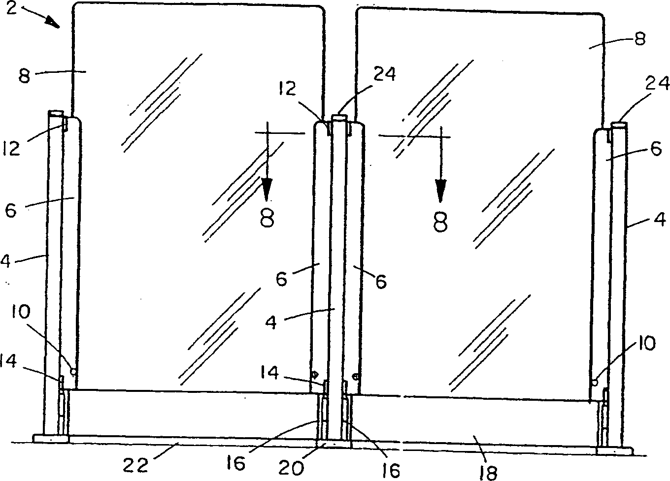
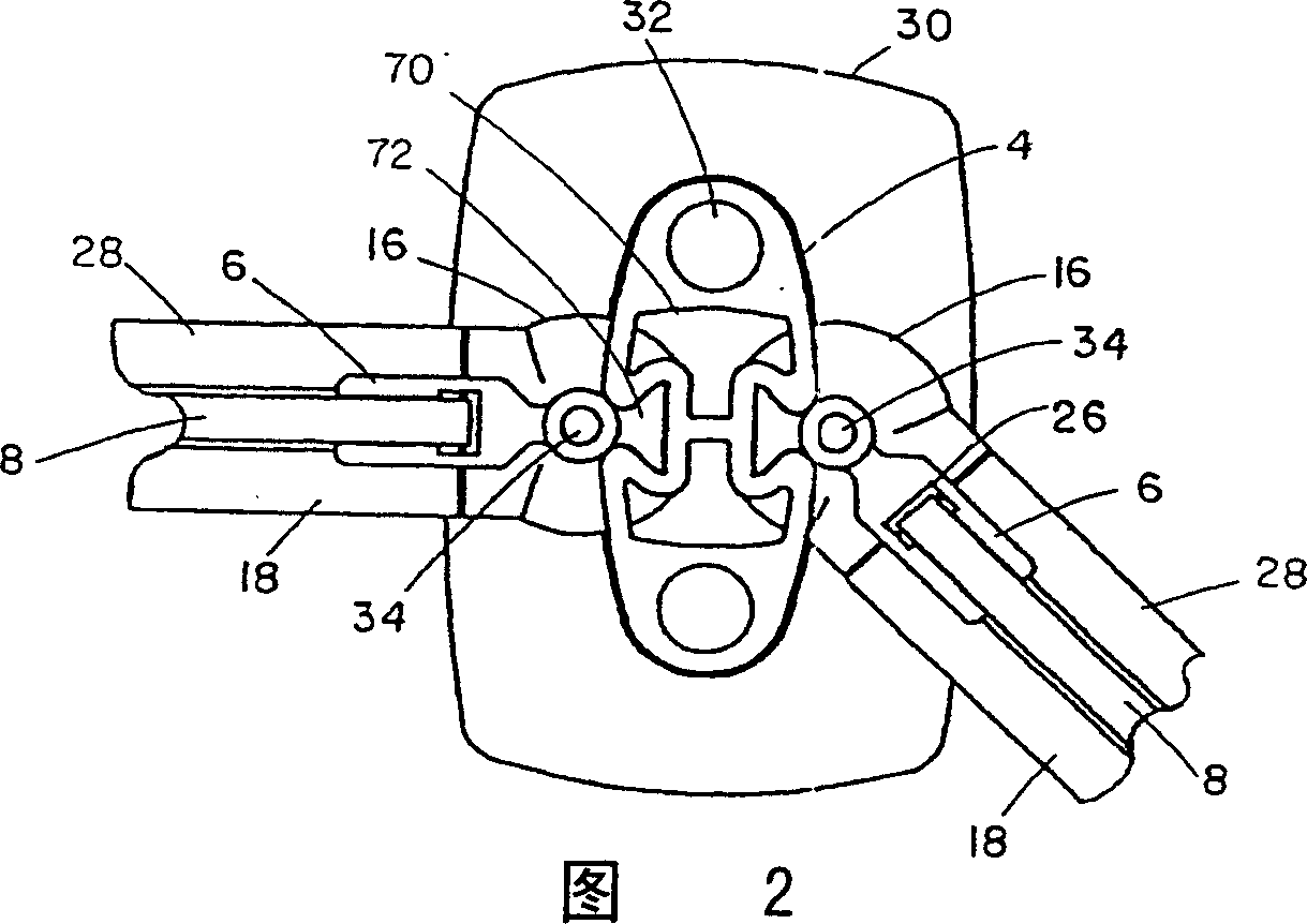
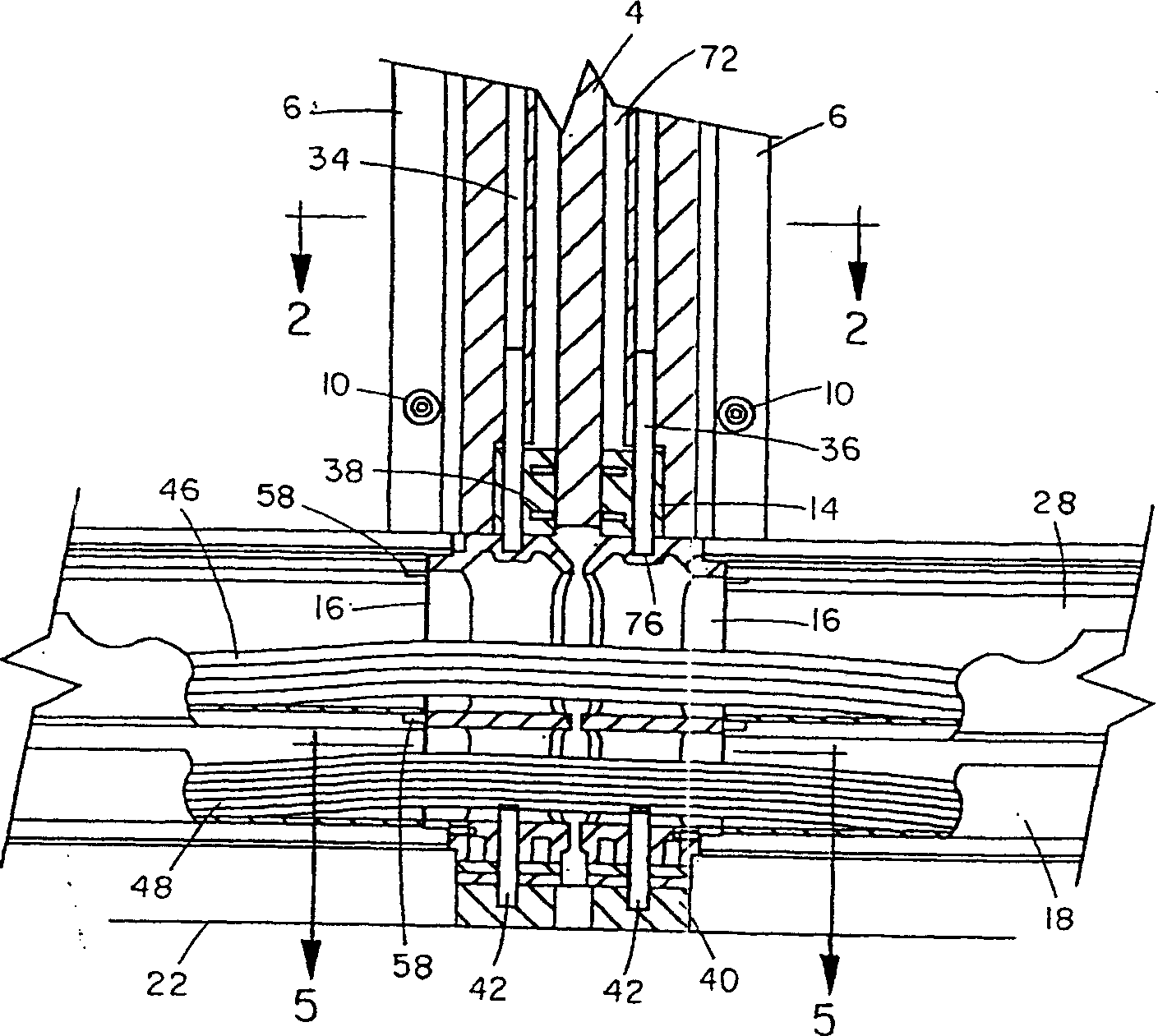
[0029] figure 1 Two component parts of a fixed barrier 2 in a preferred embodiment are shown. Each module part comprises a panel part 8 which is supported by a main post 4 on either side of the panel part 8 . In a preferred embodiment, the panel portion 8 is constructed of a clear material such as glass or plexiglass. Another embodiment of the present invention employs an opaque panel portion 8 made of other materials such as metal, wood, fabric and plastic or combinations thereof. The panel section 8 is held in place by the glass bracket extrusion 6 which is hingeably connected to the main column 4 at an upper hinge pin support 12 and a middle hinge pin support 14 . Each panel section 6 may be positioned 690 degrees from an adjacent panel section. Security screws 10 are provided to prevent the panel part 8 from being released from the glass carrier extrusion 6 . Image 6 A side view of the security screw 10 passing through the panel 8 and the glass support extrusion 6 is ...


PUM


Abstract

A fixed barrier (2) module includes a support post (4) for supporting two adjacent panels (8) each of which are hingeable. A cut-away portion in a base portion of the support post accepts two cable-carrying swivel joints (16) that are utilized as cable conduits through the support post. The swivel joints rotate with the panels, and allow cables (46, 48) to follow the fixed barrier contour. Cable carrier extrusions (28) attach to the swivel joints to extend the cable conduit below a panel section and to an adjacent support post. The swivel joints and hingeable panels allow the fixed barrier to change direction to follow any desired contour using a single-type of a support post.

Description

Background of the invention [0001] The present invention relates generally to a fixed barrier and more particularly to a modular barrier system with hinged panels, cable support castings and extrusions which can be provided for creating barriers of any profile and which can be installed to enable commercial Service disruption is minimized. [0002] Component barrier systems known in the art can be used as permanent or non-permanent dividers. In large-scale transit stations, fixed barrier systems guiding passengers to the entrances ensure normal operation of payment for transit services. Free standing barrier systems of the prior art provide a convenient and low cost alternative to erecting a permanent wall. A typical component system consists of panels that fit into connecting spines. Spines A variety of different spine types are available to connect panels at specific angles. For example, a first type of spine may have grooves 180 degrees apart to provide a straight conne...

Claims


Application Information

Patent Timeline
IPC IPC(8): E04B2/74
CPCE04B2002/7488E04B2/7435E04B2/7442
Inventor A·曼利M·惠勒
Owner CUBIC CORPORATION
Why Eureka
Try Eureka