
Simultaneous sensing and data transmission

a sensing and data technology, applied in the field of communication systems, can solve problems such as under-utilization of the channel for transmitting digital data, and achieve the effects of reducing interruption and transmission delays, increasing transmission throughput, and minimal interferen

Active Publication Date: 2014-04-01
STMICROELECTRONICS SRL
View PDF64 Cites 2 Cited by
  • Summary
  • Abstract
  • Description
  • Claims
  • Application Information

AI Technical Summary

Benefits of technology

This patent aims to improve transmission speed and minimize interference. The technical effect of the invention is to increase the amount of data that can be transferred quickly and without causing delays or interfering with other signals.

Problems solved by technology

A single channel WRAN is effective in protecting incumbent services, but halting operations or data transmissions during a quiet time results in underutilization of the channel to transmit digital data (e.g., in about every two second period there is up to 100 milliseconds without transmissions).

Method used


Image

  • Simultaneous sensing and data transmission
  • Simultaneous sensing and data transmission
  • Simultaneous sensing and data transmission

Examples


Embodiment Construction

[0024]Reference will now be made in detail to an embodiment of the present invention, examples of which are illustrated in the accompanying drawings.

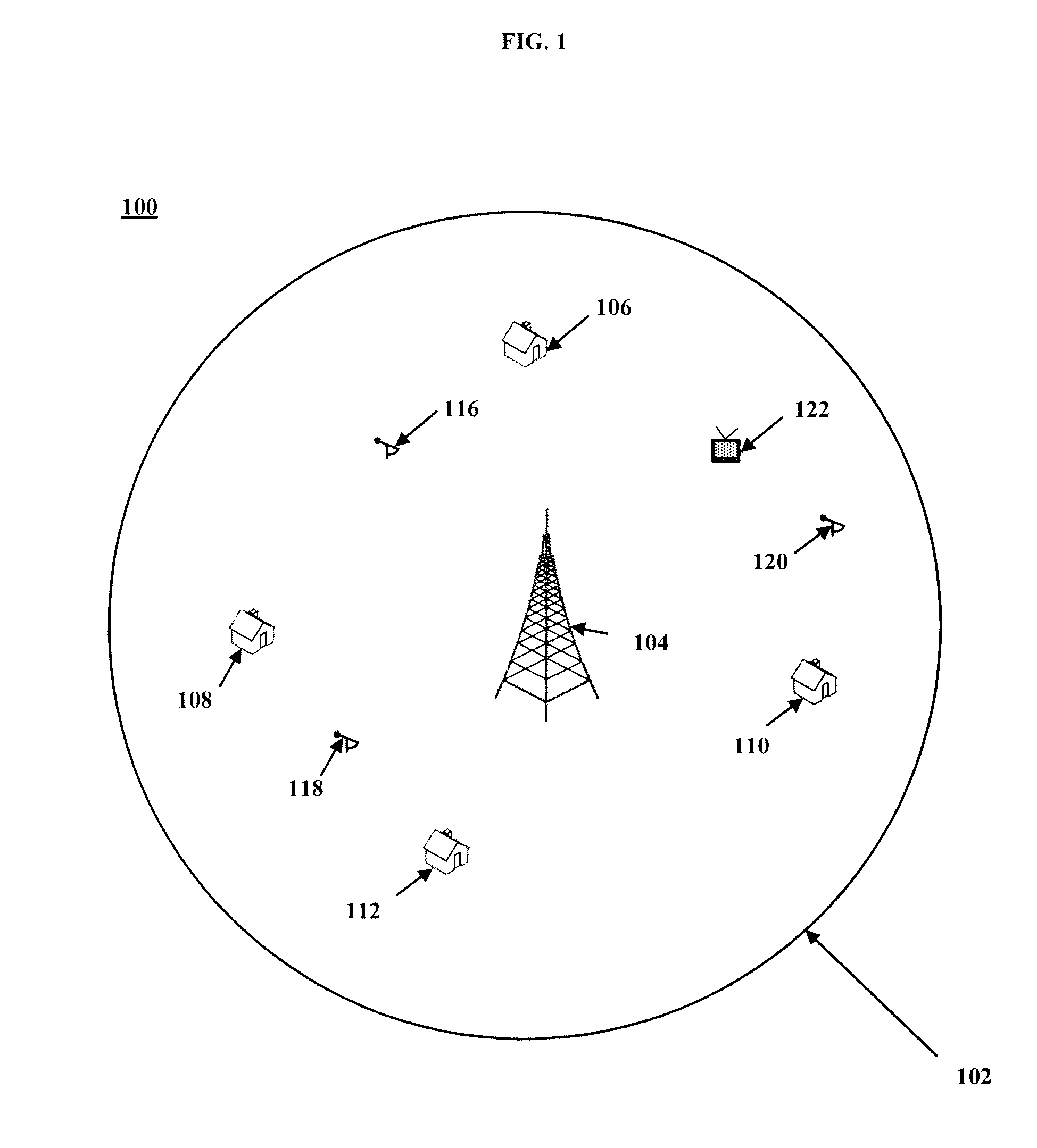
[0025]FIG. 1 illustrates a system 100 having a service area 102. Typically, the service area includes about a 30 km to 70 km coverage area or larger. In this embodiment, the service area 102 is a WRAN cell and includes a BS 104 and a plurality of CPEs 106, 108, 110, and 112 scattered throughout the service area 102. There is also a plurality of part 74 devices, e.g., microphones, 116, 118, and 120 scattered throughout the service area 102. In addition, there is also digital television (DTV) receiver 122 within the service area 102.

[0026]The BS 104 and associated CPEs 106, 108, 110, and 112 that communicate to the BS 104 via fixed point-to-multiple radio air interface are not shown in detail in FIG. 1, but in IEEE 802.22 embodiments include, e.g., a transmitter and receiver equipment to facilitate communication over the TV band. The BS 1...


PUM


Abstract

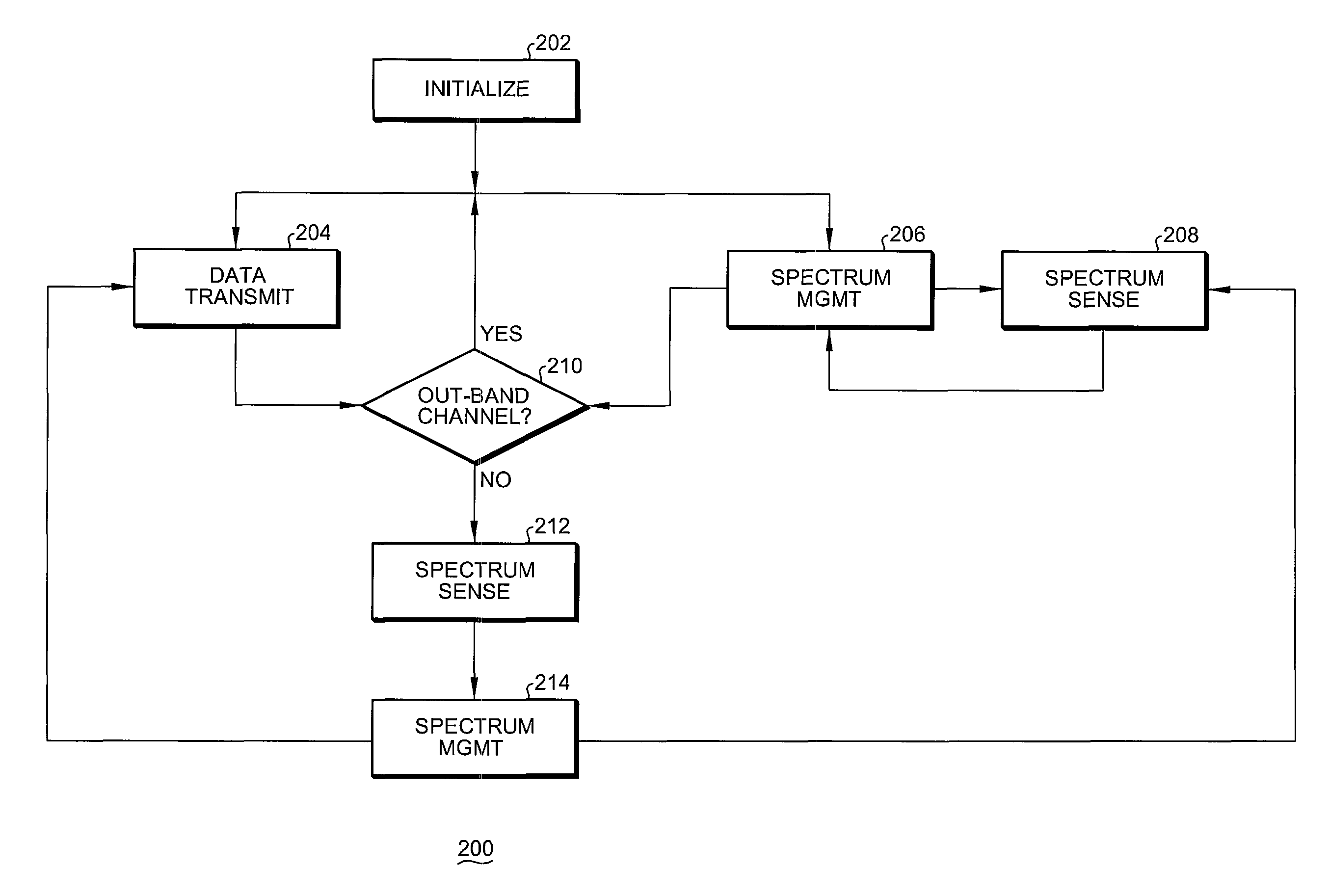
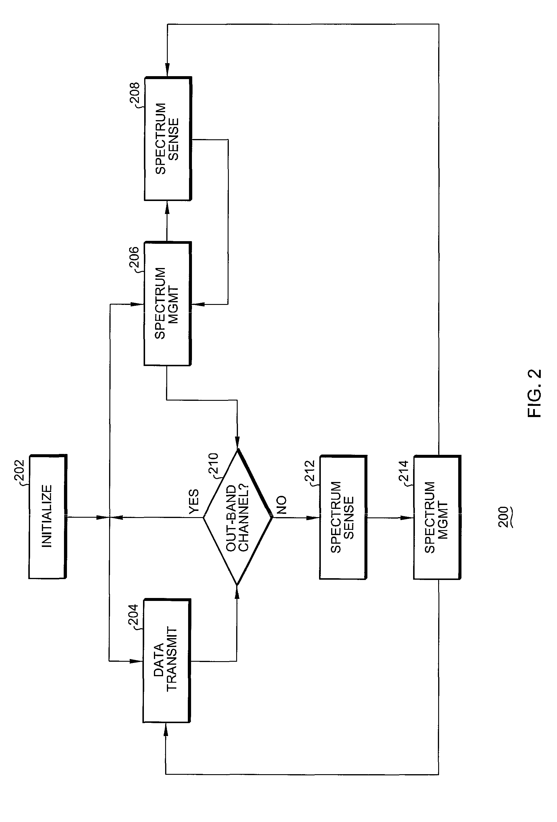
In order to satisfy the conflicting requirements for spectrum sensing and QoS of data transmission, it is highly desirable for a cognitive radio system, e.g. IEEE 802.22 WRAN, to perform spectrum sensing and data transmission simultaneously. Embodiments of the invention address critical issues of self-interference generated from a transmission unit to the co-located sensing unit when the simultaneous sensing and data transmission technique is applied. A number of interference mitigation techniques are described and analysis are given.

Description

[0001]This application claims the benefit of U.S. Provisional Patent Application No. 60 / 884,160, filed on Jan. 9, 2007, which is hereby incorporated by reference for all purposes as if fully set forth herein.BACKGROUND OF THE INVENTION[0002]1. Field of the Invention[0003]The invention relates, in general, to communication systems that include cognitive radios and / or software defined radios (SDRs) to achieve efficient and reliable spectrum use without harmful interference to incumbent services such as television (TV) receivers. More particularly, the invention relates to a method, and systems / devices configured to perform such a method, for controlling spectrum use by base stations and consumer premise equipment so as to allow unlicensed radios or other communication devices to operate in broadcast bands previously set aside for licensed users or services such as the TV broadcast bands. The method and related systems may be developed in some embodiments to comply with standards and p...

Claims


Application Information

Patent Timeline
Patent Type & Authority Patents(United States)
IPC IPC(8): G06F15/16H04W72/08G06F15/173H04W4/00H04W16/14H04W72/54
CPCH04W72/082H04W16/14H04W72/085H04W72/542H04W72/541
Inventor HU, WENDONG
Owner STMICROELECTRONICS SRL
Learn More