Vision system integration

a vision system and vision system technology, applied in the direction of vehicle position/course/altitude control, process and machine control, instruments, etc., can solve the problems of requiring time-consuming, burdensome installation and separate power sources, and prone to physical damage of markers, so as to minimize installation costs and operational interruptions, minimize the reliance on collision sensors, and maximize precision

Active Publication Date: 2022-06-07
HYDRO GEAR PARTNERSHIP
View PDF23 Cites 1 Cited by
  • Summary
  • Abstract
  • Description
  • Claims
  • Application Information

AI Technical Summary

Benefits of technology

[0010]Each approach presents unique problems and all of these approaches lack any reliable way to address temporary obstacles and periodic changes to a lawn. A system should account for unexpected, continual changes all lawns present, while minimizing the reliance on a collision sensor. This system should minimize installation costs and operational interruptions, whether those hindrances stem from electronic interference with underground markers or physical obstructions to GPS. Finally, the system should maximize precision by mowing as near as possible to obstacles and borders.

Problems solved by technology

But these markers require time-consuming, burdensome installation and a separate power source.
This field is vulnerable to interference from underground ferromagnetic materials and neighboring marker systems.
In addition, the markers are vulnerable to physical damage from gardening activities or excavation and may require maintenance.
As a result, underground markers can suffer downtime.
Reliance on GPS, however, risks signal distortions and reflections, given the landmarks, walls, and tree canopies, among other obstructions, in many lawns.
Further, without the most power-hungry and expensive equipment, a GPS-guided autonomous lawn mower cannot approach optimal mowing precision.
In short, many autonomous lawn mowers lack any actual navigation system, like the three mentioned previously, or otherwise.
This risks damaging those objects, and the lawn mowers themselves.
Each approach presents unique problems and all of these approaches lack any reliable way to address temporary obstacles and periodic changes to a lawn.

Method used


Image

  • Vision system integration
  • Vision system integration
  • Vision system integration

Examples


Embodiment Construction

[0018]This description describes one or more embodiments and should not limit the invention to those embodiments. The description explains principles of the invention to enable one of ordinary skill in the art to understand and apply the principles to practice both the described embodiments and other embodiments that may come to mind. The invention's scope should cover all embodiments that might fall within the scope of the claims, either literally or under the doctrine of equivalents.

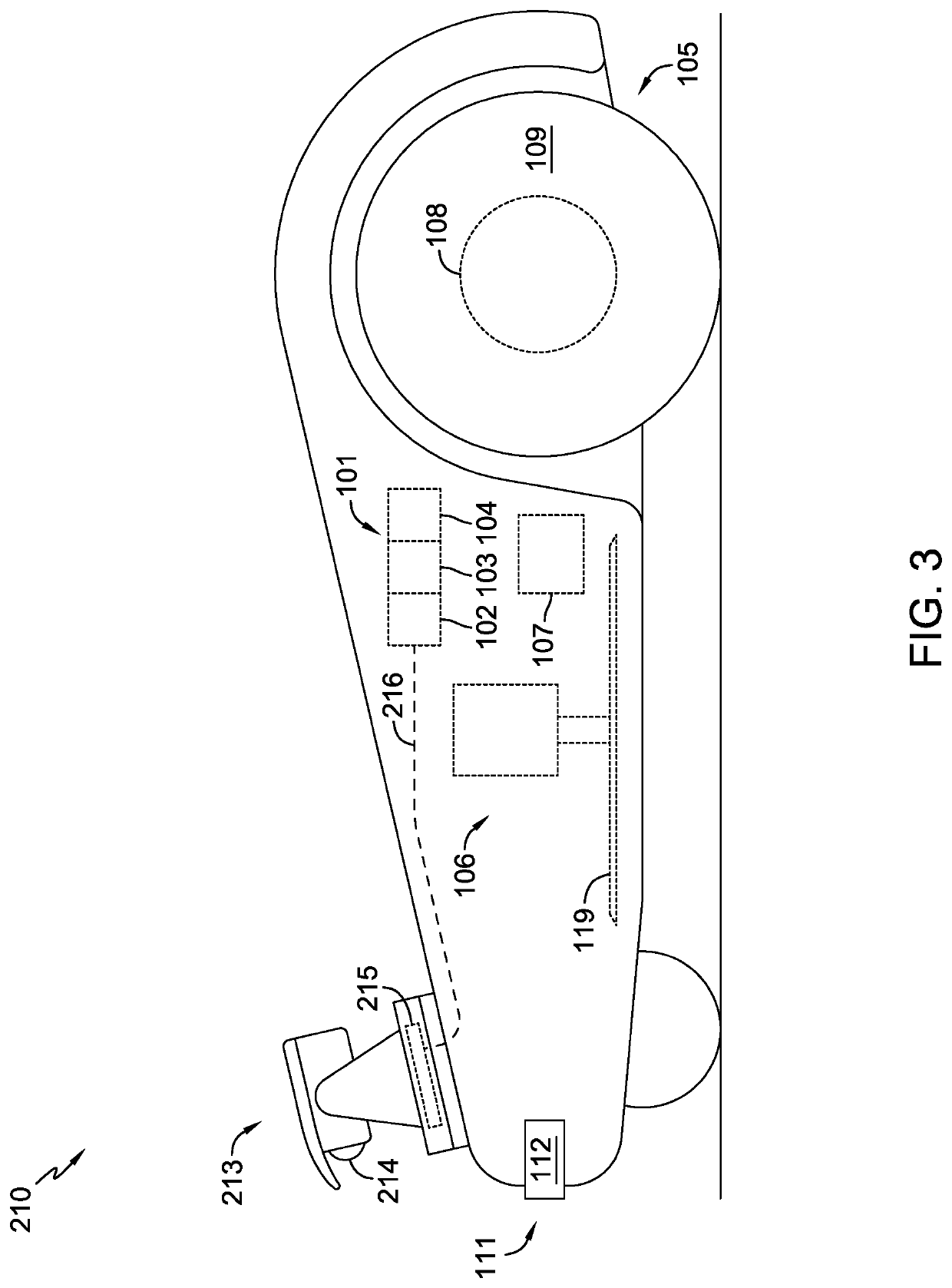
[0019]An exemplary embodiment combines a system similar to collision assembly 111, in FIG. 1, with a vision assembly. The collision sensor can be a displacement sensor (a Hall effect sensor, for example) that provides a signal to the main processor of an autonomous lawn mower upon collision. For a particular depiction, FIG. 1 shows a side view of autonomous lawn mower 110. Lawn mower 110 includes main board 101, drive system 105, blade system 106, and collision assembly 111. Collision assembly 111 incl...


PUM


Abstract

A control system including a drive system and a blade system; a collision sensor; a main board having a main processor and in communication with the collision sensor, the drive system, and the blade system; the collision sensor, upon sensing a collision, capable of transmitting a collision signal to the main processor; the main board capable of transmitting an adjustment command to the drive system or the blade system; a vision sensor; a vision processor in communication with the vision sensor and the main processor, and capable of determining whether the image data represent an obstacle; the vision sensor capable of transmitting image data to the vision processor; when the vision processor determines the image data represent an obstacle, the vision processor capable of transmitting a collision-replicating signal to the main processor, prompting the main board to transmit the adjustment command to the drive system and/or the blade system.

Description

CROSS REFERENCE[0001]This application claims the benefit of U.S. Provisional Patent Application No. 62 / 691,445, filed on Jun. 28, 2018. The contents of this prior application is incorporated herein by reference in its entirety.FIELD OF THE INVENTION[0002]This application relates to autonomous lawn vehicles, a category that includes lawn mowers, tractors, and landscaping machinery.BACKGROUND AND SUMMARY[0003]The lawn mower industry continues to seek ways to ease users' physical burdens. Thus, lawn mowers have undergone an automation evolution, starting with self-propulsion, with recent developments signaling a movement towards unmanned (or autonomous) technology. These developments aim to purge physical labor from lawn mowing, at least as much as possible.[0004]Autonomous lawn mowers typically include collision systems positioned at the front (although these can also appear on the sides or rear), similar to the bumpers on most automobiles. The collision system on an autonomous lawn m...

Claims


Application Information

Patent Timeline
Patent Type & Authority Patents(United States)
IPC IPC(8): A01D34/00G05D1/00G05D1/02A01D34/82A01D34/64A01D101/00
CPCA01D34/008A01D34/64A01D34/82A01D34/828G05D1/0055G05D1/0088G05D1/0214A01D2101/00G05D1/0231G05D1/0255G05D1/0257G05D2201/0208G05D1/0246A01D75/185
Inventor HOYDA, DAMON J.
Owner HYDRO GEAR PARTNERSHIP
Why Eureka
Try Eureka