
Fuel cell architectures, thermal systems, and control logic for efficient heating of fuel cell stacks

a fuel cell and stack technology, applied in the field of fuel cell systems, can solve the problems of increasing design complication, reducing system efficiency, and significant drop in stack output voltage and power, so as to improve fuel cell system reliability, reduce start up time, and increase system heating efficiency

Active Publication Date: 2019-10-15
GM GLOBAL TECH OPERATIONS LLC
View PDF3 Cites 0 Cited by
  • Summary
  • Abstract
  • Description
  • Claims
  • Application Information

AI Technical Summary

Benefits of technology

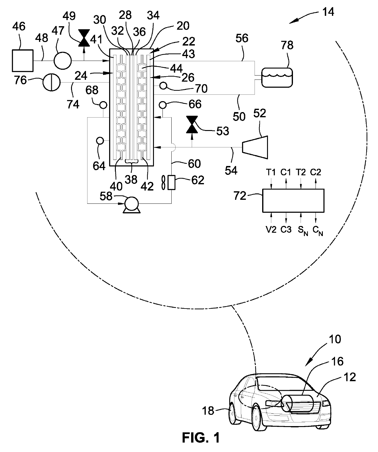
[0001]The present disclosure relates generally to fuel cell systems for converting chemical energy of gaseous hydrogen-based fuels into electricity. More specifically, aspects of this disclosure relate to thermal systems and related control algorithms for efficiently heating fuel cell stacks.
[0002]Current production motor vehicles, such as the modern-day automobile, are originally equipped with a powertrain that operates to propel the vehicle and power the onboard vehicle electronics. The powertrain, which is inclusive of, and oftentimes misclassified as, a vehicle drivetrain, is generally comprised of a prime mover that delivers driving power to the vehicle's final drive system (e.g., differential, axle, and road wheels) through a multi-speed power transmission. Automobiles have generally been powered by a reciprocating-piston type internal combustion engine (ICE) because of its ready availability and relatively inexpensive cost, light weight, and overall efficiency. Such engines include two and four-stroke compression-ignited (CI) diesel engines, four-stroke spark-ignited (SI) gasoline engines, six-stroke architectures, and rotary engines, as some non-limiting examples. Hybrid and electric vehicles, on the other hand, utilize alternative power sources, such as an electric motor-generator, to propel the vehicle and minimize reliance on an engine for power and, thus, increase overall fuel economy.
[0005]To generate the requisite electricity for powering a motor vehicle, numerous fuel cells are typically combined, in series or in parallel, into a fuel cell stack to achieve a higher output voltage and allow for stronger current draw. For example, a typical fuel cell stack for an automobile may have two hundred or more stacked fuel cells. These fuel cell stacks receive reactant gas as a cathode input, typically as a flow of ambient air or concentrated gaseous oxygen forced through the stack by a compressor. During normal operation, a quantifiable mass of the oxygen is not consumed by the stack; some of the remnant oxygen is output as cathode exhaust gas that may include water as a stack by-product. The fuel cell stack also receives hydrogen or hydrogen-rich reactant gas as an anode input that flows into the anode side of the stack. The distribution of hydrogen within the anode flow channels is typically held substantially constant for proper fuel cell stack operation. In some operational modes, supplementary hydrogen is fed into the fuel cell stack so that the anode gas is evenly distributed to achieve a calibrated stack output load. However, with this additional hydrogen input, the amount of hydrogen that “slips” to the anode's exhaust is increased, which can lead to reduced system efficiency.
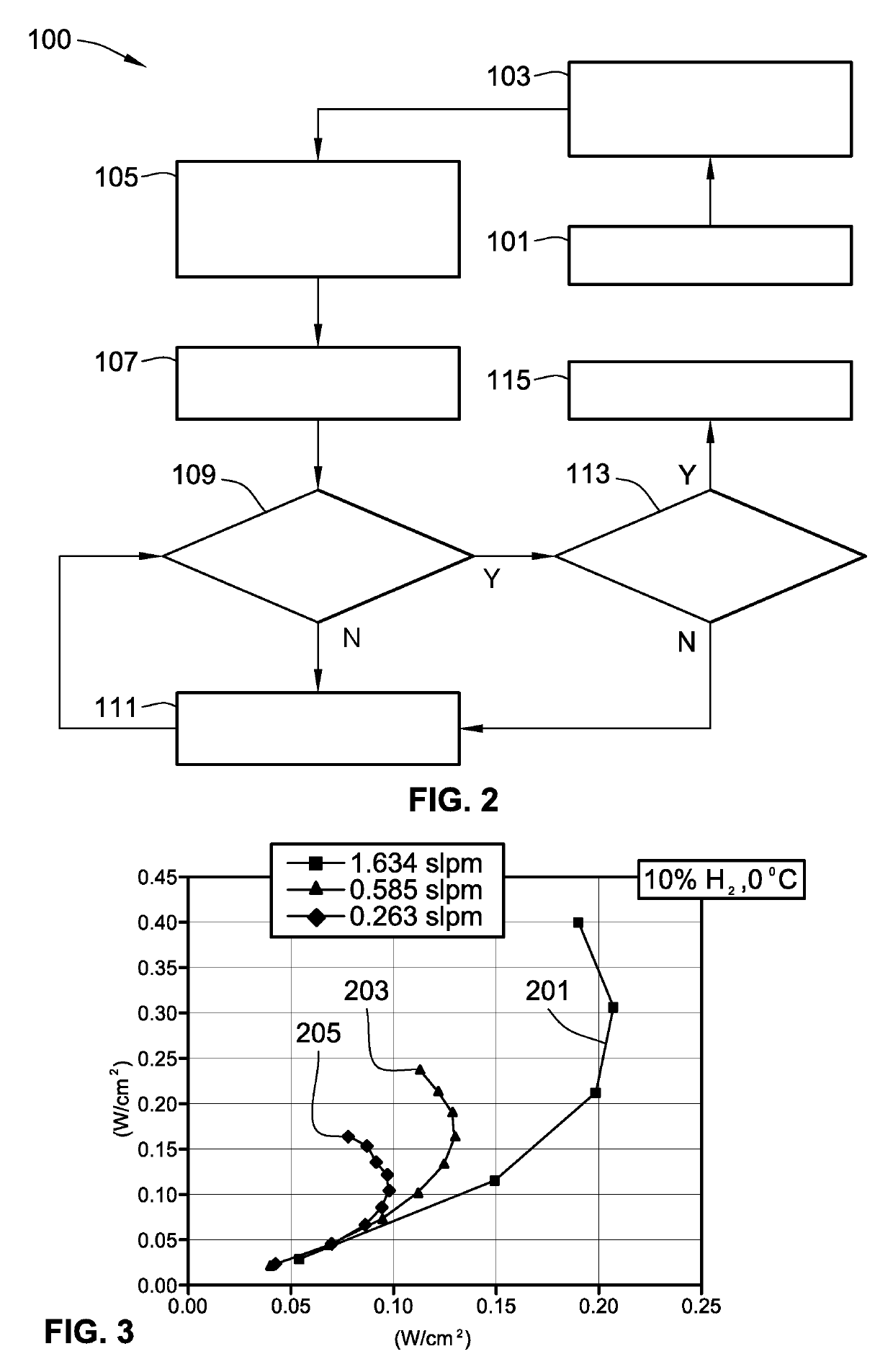
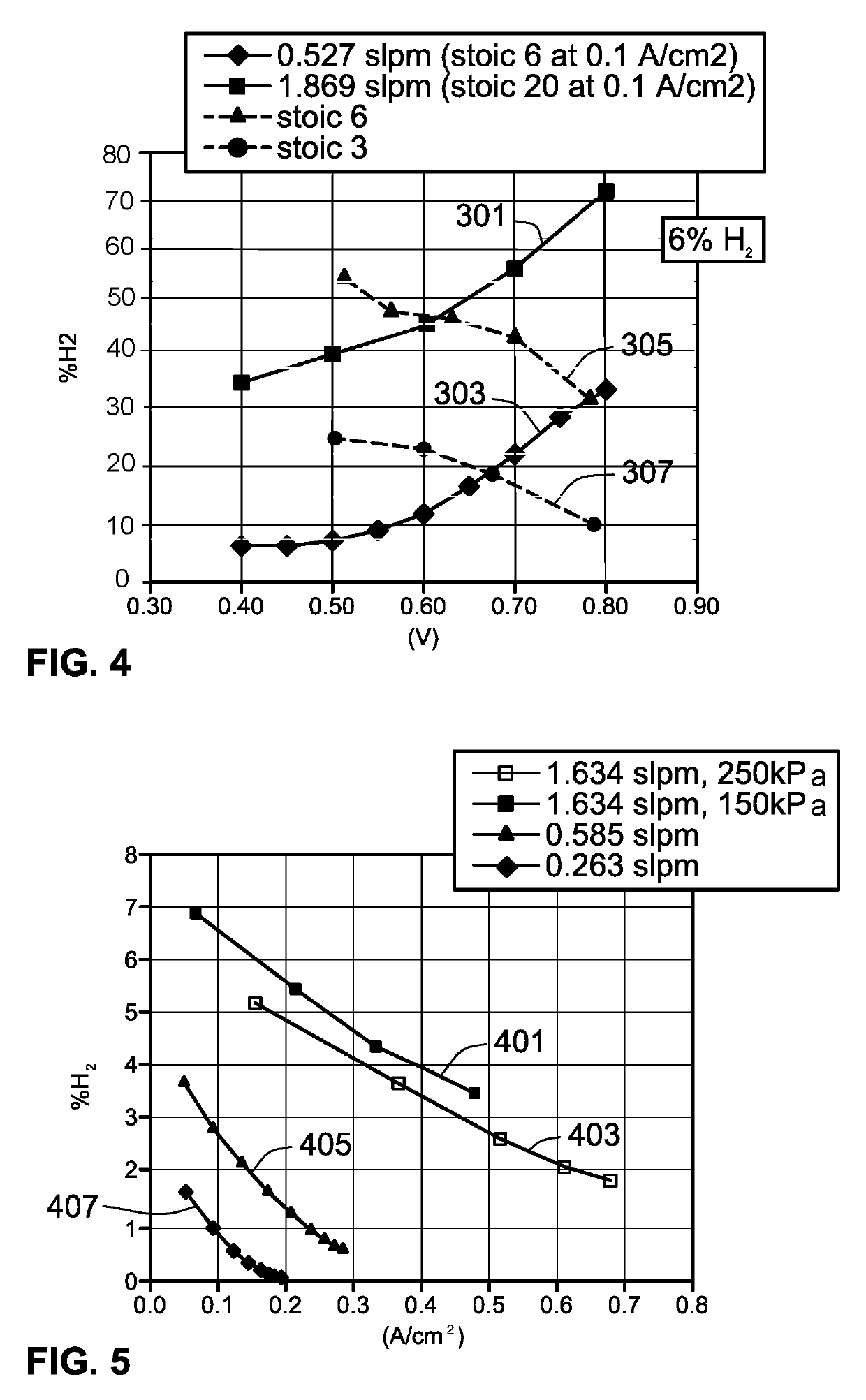
[0009]Attendant benefits for at least some of the disclosed concepts include improved fuel cell system reliability, increased system heating efficiency, reduced start up time during cold / freeze starts, decreased system emissions, and reduced overall system costs. Other attendant benefits may include minimizing the impact of environmental variations and replaceable component failure by eliminating system dependence on a dedicated electrical heating deceive. Disclosed control procedures also help to increase freeze start efficiency by using less hydrogen-based fuel. At −30C, with a bleed of approximately 6-15% H2 (e.g., 10% H2) in the cathode, while operating at a CD of approximately 0.15 A / cm2 and reducing the flow rate from approximately 1.6 (or Stoic 10) to approximately 0.6 (Stoic 5) standard liter per minute (SLPM), for example, outlet % H2 is reduced from 5% to approximately 1.8% while concomitantly increasing fraction of waste heat to achieve effective stack heating. The term “waste heat,” as used herein, can be typified as heat generated as an ancillary byproduct of a chemical reaction in a system process that is not specifically designed to generate heat.

Problems solved by technology

However, with this additional hydrogen input, the amount of hydrogen that “slips” to the anode's exhaust is increased, which can lead to reduced system efficiency.
For fuel cell “cold start”—system start-up in freezing temperatures, e.g., at or below 0° C.—the cooling fluid in the coolant loop and stack is very cold; if the pump is immediately started, the cooling fluid may have a quenching effect on the fuel cell reaction that may cause a significant drop in stack output voltage and power.
However, such devices increase design complication and add to the overall cost of the system.
Some of the bled hydrogen gas will not react in the cathode and, thus, may be lost to cathode exhaust.
Additionally, in instances where hydrodynamic residence time of hydrogen is slow, additional H2 slip may occur at high flow rates before it reacts.

Method used


Image

  • Fuel cell architectures, thermal systems, and control logic for efficient heating of fuel cell stacks
  • Fuel cell architectures, thermal systems, and control logic for efficient heating of fuel cell stacks
  • Fuel cell architectures, thermal systems, and control logic for efficient heating of fuel cell stacks

Examples


Embodiment Construction

[0022]This disclosure is susceptible of embodiment in many different forms. There are shown in the drawings and will herein be described in detail representative embodiments of the disclosure with the understanding that these representative embodiments are to be considered an exemplification of the principles of the disclosure and are not intended to limit the broad aspects of the disclosure to the embodiments illustrated. To that extent, elements and limitations that are disclosed, for example, in the Abstract, Summary, and Detailed Description sections, but not explicitly set forth in the claims, should not be incorporated into the claims, singly or collectively, by implication, inference or otherwise. For purposes of the present detailed description, unless specifically disclaimed: the singular includes the plural and vice versa; the words “and” and “or” shall be both conjunctive and disjunctive; the word “all” means “any and all”; the word “any” means “any and all”; and the word...


PUM

PropertyMeasurementUnit
cell voltageaaaaaaaaaa
temperatureaaaaaaaaaa
freezing temperaturesaaaaaaaaaa

Abstract

Disclosed are fuel cell architectures, thermal sub-systems, and control logic for regulating fuel cell stack temperature. A method is disclosed for regulating the temperature of a fuel cell stack. The method includes determining a pre-start temperature of the fuel cell stack, and determining, for this pre-start temperature, a target heating rate to heat the stack to a calibrated minimum operating temperature. The method then determines a hydrogen bleed percentage for the target heating rate, and executes a stack heating operation including activating the fuel cell stack and commanding a fluid control device to direct hydrogen to the cathode side at the hydrogen bleed percentage to generate waste heat. After a calibrated period of time, the method determines if an operating temperature of the stack exceeds the calibrated minimum stack operating temperature. Responsive to the operating temperature being at or above the minimum operating temperature, the stack heating operation is terminated.

Description

INTRODUCTION[0001]The present disclosure relates generally to fuel cell systems for converting chemical energy of gaseous hydrogen-based fuels into electricity. More specifically, aspects of this disclosure relate to thermal systems and related control algorithms for efficiently heating fuel cell stacks.[0002]Current production motor vehicles, such as the modern-day automobile, are originally equipped with a powertrain that operates to propel the vehicle and power the onboard vehicle electronics. The powertrain, which is inclusive of, and oftentimes misclassified as, a vehicle drivetrain, is generally comprised of a prime mover that delivers driving power to the vehicle's final drive system (e.g., differential, axle, and road wheels) through a multi-speed power transmission. Automobiles have generally been powered by a reciprocating-piston type internal combustion engine (ICE) because of its ready availability and relatively inexpensive cost, light weight, and overall efficiency. Su...

Claims


Application Information

Patent Timeline
Patent Type & Authority Patents(United States)
IPC IPC(8): H01M8/04H01M8/04701B60L58/31B60L58/34H01M8/04992B60L3/12H01M8/04302H01M8/0432H01M8/04746
CPCH01M8/04225H01M8/04007H01M8/04268H01M2250/20H01M8/04731B60L2240/80B60L58/31B60L58/34B60L2270/12H01M8/04302B60L2240/36H01M8/04365H01M8/04753Y02T90/40Y02E60/50B60L2270/10B60L3/12H01M8/04992H01M2250/402
Inventor ARISETTY, SRIKANTHROGAHN, AARON R.LAKSHMANAN, BALASUBRAMANIAN
Owner GM GLOBAL TECH OPERATIONS LLC
Learn More