
Equipment shelf-resident network interface unit by-pass circuit

Active Publication Date: 2006-09-05
ADTRAN
View PDF4 Cites 4 Cited by
  • Summary
  • Abstract
  • Description
  • Claims
  • Application Information

AI Technical Summary

Benefits of technology

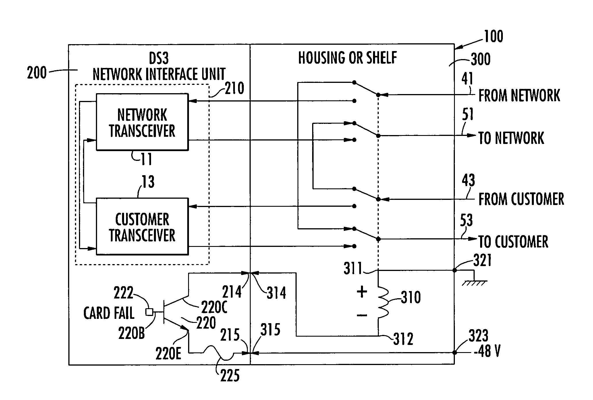
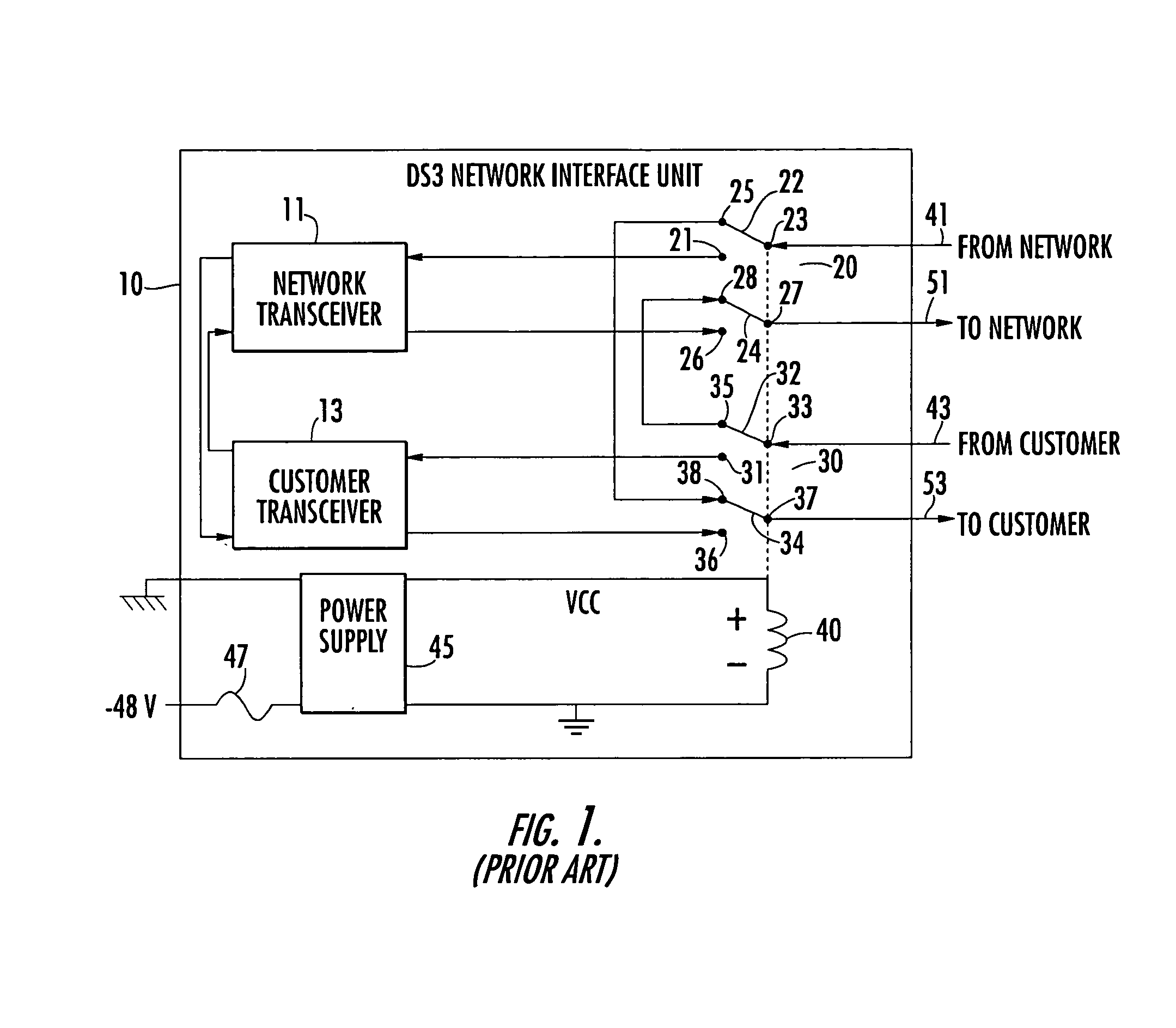
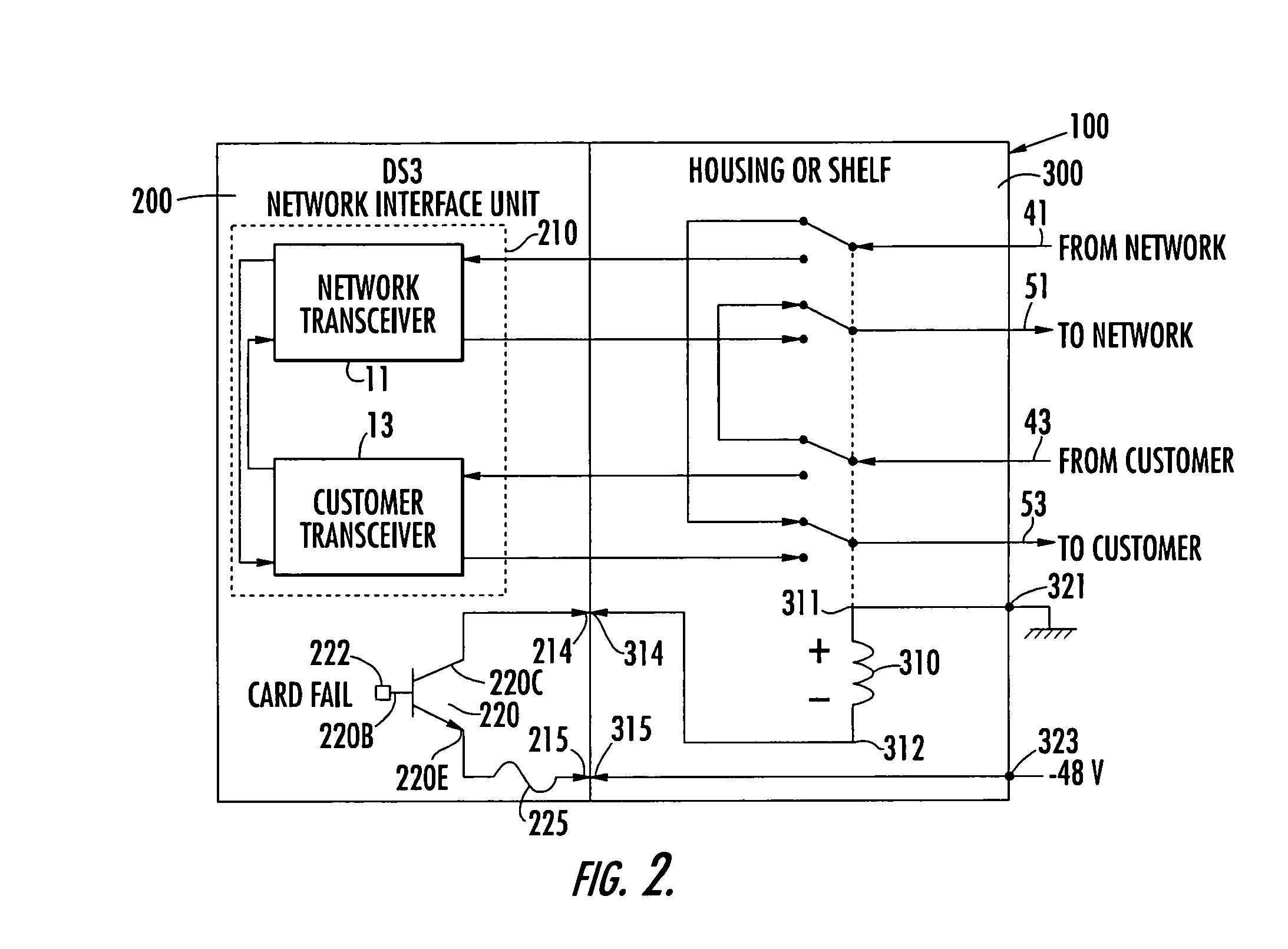
[0007]In accordance with the present invention, these and other shortcomings of the prior art NIU by-pass architecture of FIG. 1 are effectively overcome by a new and improved NIU by-pass arrangement that is configured to by-pass the NIU in the event of a variety of abnormal or malfunction c

Problems solved by technology

However, due to the possibility of an NIU card failure or some external event such as a power interruption, adding an NIU to the monitored circuit constitutes a potential failure point.
Now, although the NIU-associated switching architecture of FIG. 1 will perform its intended by-pass functionality should there be a power supply failure, because the NIU by-pass relay 40 is physically install

Method used


Image

  • Equipment shelf-resident network interface unit by-pass circuit
  • Equipment shelf-resident network interface unit by-pass circuit
  • Equipment shelf-resident network interface unit by-pass circuit

Examples


second embodiment

[0025]FIG. 3 illustrates the configuration of the invention, in which a failure indicator 230, such as a FAIL LED, is installed on the NIU card 200, and an associated LED control circuit 330 is incorporated into the shelf-resident by-pass relay circuit 300. As shown therein, the LED 230 has its cathode 231 coupled through a resistor 240 to the (−48V) connection port 215, and its anode 232 coupled to an LED control port 216 of the NIU card 200. The LED control circuit 330 includes a control device, shown as an NPN bipolar transistor 340, having its emitter 340E coupled to an LED control port 316, which is arranged to be coupled in circuit with the LED control port of the NIU card 200, when the NIU card is installed in its card slot. Transistor 340 has its collector 340C coupled to GND and through a resistor 350 to its base 340B and to the anode 361 of a reverse blocking diode 360, the cathode 362 of which is coupled to the connection port 314.

first embodiment

[0026]In the circuit of FIG. 3, assuming that the NIU is installed in its card slot and power is available from the (−48V) power supply, then in response to the CARD FAIL signal being asserted high, transistor 220 will turn on, providing a current path for energizing the relay coil 310, as in the first embodiment, described above. This, in turn, pulls the base 340B of transistor 340 low, turning it off and interrupting a current path for the FAIL LED 230.

[0027]On the other hand, when the CARD FAIL input to the base 220B of transistor 220 is asserted low, transistor 220 will be turned off, so that there is no current path for energizing current for the relay coil 310. With no current path through relay coil 310, the base 340B of the transistor 340 will be pulled high, turning it on and providing a current path for the FAIL LED 230, so as to alert personnel of an NIU card failure. In this condition, the reverse blocking diode 360 serves to prevent current from flowing through the rela...


PUM


Abstract

A (DS3) network interface unit (NIU) by-pass architecture places the NIU on its own circuit card and exclusive of by-pass switching (and relay) components, which are installed in the equipment shelf, proper, so that physical removal of the NIU card will leave the by-pass circuitry intact. The by-pass circuit responds to an abnormality of the NIU card, such as malfunction or physical removal of the NIU from its card slot, and also to a power supply failure. It also contains an indicator to draw attention to a failed NIU, increasing the likelihood that someone will notice a damaged card.

Description

CROSS-REFERENCE TO RELATED APPLICATION[0001]The present application claims the benefit of copending U.S. Provisional Patent Application Serial No. 60 / 313,100, filed Aug. 17, 2001, by David E. Jones et al, entitled: “DS3 NETWORK INTERFACE UNIT BY-PASS WITHIN HOUSINGS AND SHELVES,” assigned to the assignee of the present application and the disclosure of which is incorporated herein.FIELD OF THE INVENTION[0002]The present invention relates in general to communication systems and components therefor, and is particularly directed to a (DS3) network interface unit (NIU) by-pass arrangement, that is configured to by-pass the NIU in the event of one or more malfunction conditions, in addition to power failure, including failure and / or removal of the NIU card, so as to minimize an interruption of digital communications between respective customer and network digital communication devices over the communication circuit to which the NIU is controllably coupled.BACKGROUND OF THE INVENTION[0003...

Claims


Application Information

Patent Timeline
IPC IPC(8): H04B1/38H04B17/00H04Q7/20H04B1/00H04L12/26H04M3/00H04M3/10H04M3/12H04M19/00H04Q1/02H04Q7/00
CPCH04L12/2602H04L43/00H04M3/12H04M3/005H04L43/0817H04Q1/028H04M3/10H04M19/00
Inventor JONES, DAVID ERICMORGAN, JASON N.MURPHREE, STACY MORRISBROCK, JASON TED
Owner ADTRAN
Learn More