Timepiece movement

A technology of movement and timepiece, applied in the direction of movement size, time indication mechanism, gear mechanism, etc.

Inactive Publication Date: 2002-11-13
ETA SA MFG HORLOGERE SUISSE
View PDF0 Cites 16 Cited by
  • Summary
  • Abstract
  • Description
  • Claims
  • Application Information

AI Technical Summary

Problems solved by technology

But the disadvantage of this solution is that it requires the production of an additional part, usually a gaske

Method used


Image

  • Timepiece movement
  • Timepiece movement
  • Timepiece movement

Examples


Embodiment Construction

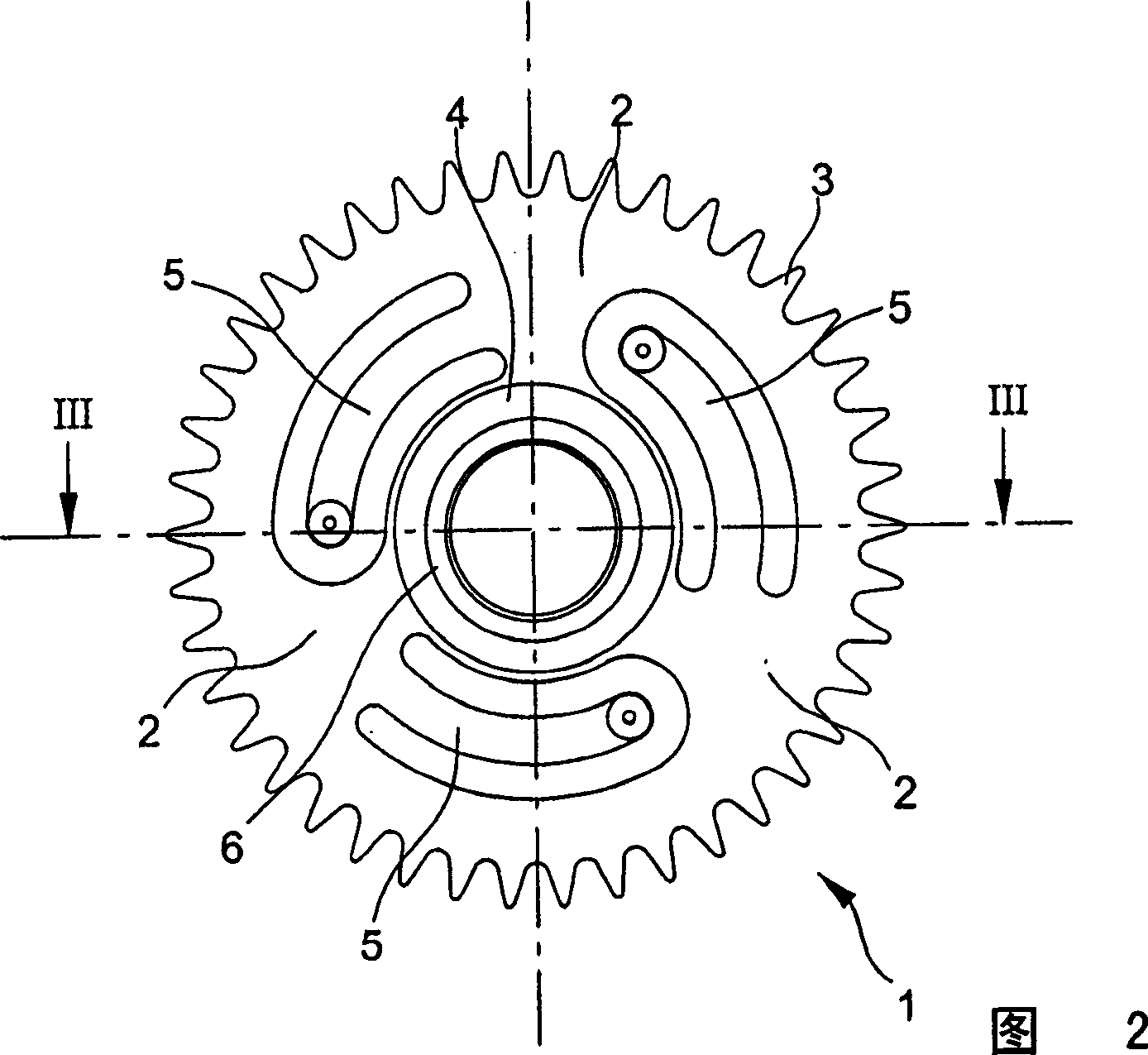
[0021] Referring to Fig. 2, the hour wheel 1 has a conventional structure. Three radial extensions 2 connect the wheel 3 to the minute pinion 4 . In the particular embodiment shown in FIG. 2 , it will be noted that there are three arms 5 , substantially in the shape of circular arcs, each extending from said radially extending portion 2 . These arms 5 have the function of adjusting the relative vertical positioning of the hour wheel 1 and of the minute pinion (not shown in this figure), thus allowing the omission of the foil springs normally used to ensure this function.

[0022] FIG. 2 also shows a specific feature of the hour wheel 1 , that is, the inner side of the minute pinion 4 includes an annular protrusion 6 .

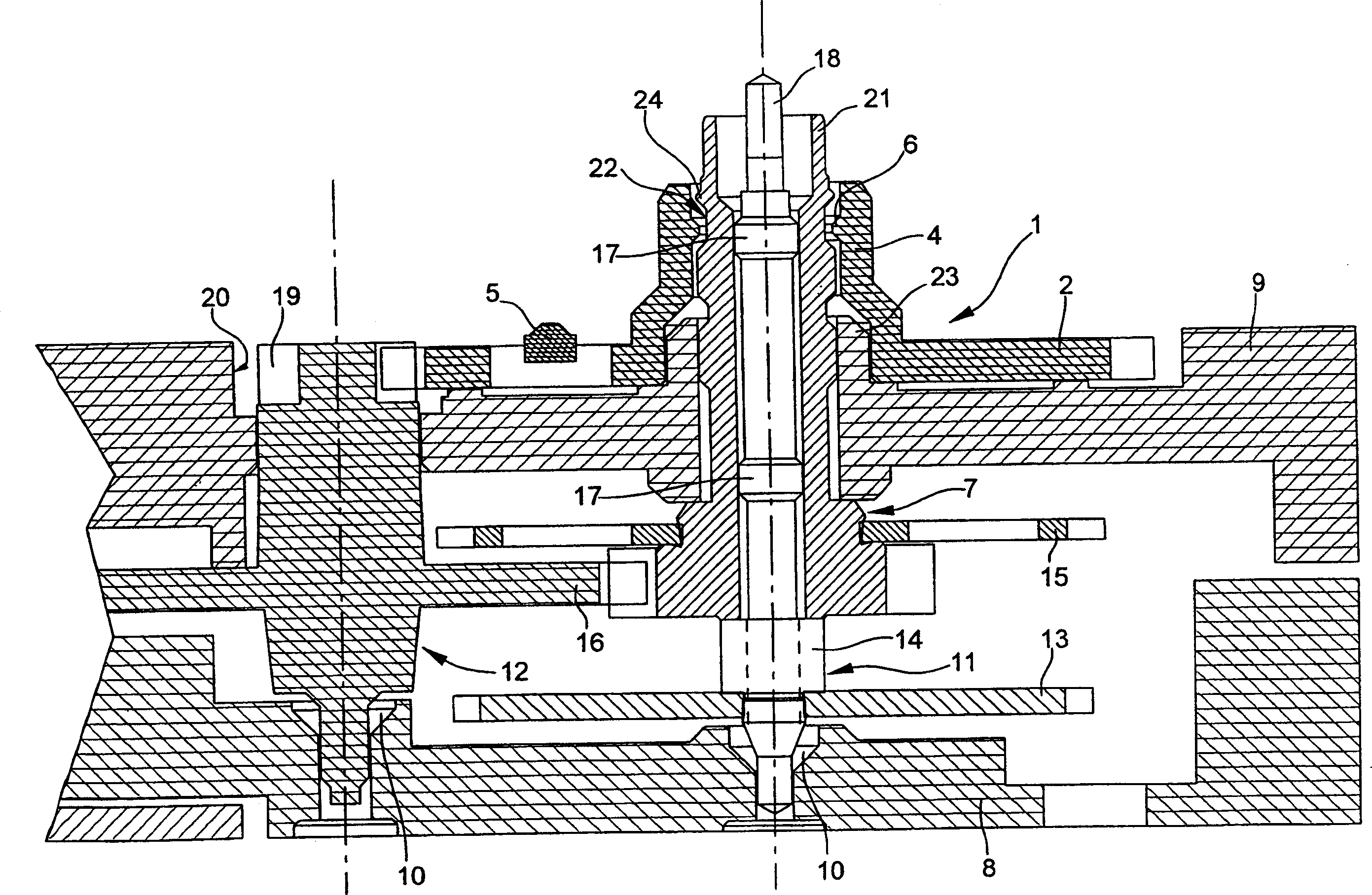
[0023] image 3 This makes it easier to understand the advantages of said protrusion 6 since it is shown in its effective position, ie when the hour wheel 1 is arranged on the minute pinion 7 .

[0024] Partially visible in this figure is the movement timepie...


PUM


Abstract

The invention relates to the structure of a timepiece movement, more specifically the structure of the hour wheel (1), the inner side of which duct (4) comprises an annular groove arranged on the outer wall of the duct (21) of the minute pinion (7) (22) Fitting annular protrusion (6). Thus, the hour wheel is snap-fitted to the movement, it is not necessary to provide additional parts for this purpose, and therefore its gear wheel (3) cannot be disengaged from the transmission wheel (19) during transport of the movement.

Description

technical field [0001] The invention relates to a timepiece movement comprising: a bridge; display means with hands; a train of wheels connecting drive means to said hands, said train of wheels comprising at least one drive wheel meshing indirectly with said drive means and Fixed to the minute pinion pivoted by a column mounted in the wheel tie bar; the hour wheel, arranged around the minute pinion and sitting on a bridge, the drive wheel and the hour wheel respectively on the two sides of said bridge side extension. Background technique [0002] Timepiece movements of this type are common and have been known for a long time. However, it should be noted that the movements of the prior art have certain deficiencies which the present invention overcomes. [0003] FIG. 1 schematically shows a part of a movement with a central seconds wheel disclosed in the prior art. Figure 1 shows the relative position of the time display wheel device. In particular, the seconds wheel devi...

Claims


Application Information

Patent Timeline
IPC IPC(8): G04B19/02G04B1/02G04B13/02G04B29/04G04B41/00
CPCG04B13/02G04B29/04G04B1/02
Inventor M·贝特利尼T·舍宁贝格
Owner ETA SA MFG HORLOGERE SUISSE
Why Eureka
Try Eureka