Tunnel drilling machine and hydraulic power head device thereof

A technology of hydraulic power head and tunnel drilling rig, which is applied to rotary drilling rigs, drill pipes, drill pipes, etc., can solve the problems of chuck failure, difficulty in ensuring the safety and reliability of tunnel drilling rigs, and large installation space.

Inactive Publication Date: 2012-01-25
SANY HEAVY EQUIP
View PDF8 Cites 8 Cited by
  • Summary
  • Abstract
  • Description
  • Claims
  • Application Information

AI Technical Summary

Problems solved by technology

[0006] from figure 1 It can be seen from the figure that due to the existence of the external hydraulic cylinder 21, the installation space required for this chuck 23 is large, which is not conducive to the structural design of the power head, and has a great impact on the drilling effect of the tunnel drilling rig; at the same time, due to the ...

Method used


Image

  • Tunnel drilling machine and hydraulic power head device thereof
  • Tunnel drilling machine and hydraulic power head device thereof
  • Tunnel drilling machine and hydraulic power head device thereof

Examples


Embodiment Construction

[0030] The core of the present invention is to provide a hydraulic power head device for tunnel drilling rigs, which can clamp drill pipes stably and effectively, and has good safety and reliability. Another core of the present invention is to provide a tunnel drilling machine including the above-mentioned hydraulic power head device.

[0031] The orientation words such as the advancing side and the retreating side involved in this article are defined based on the direction when the drill pipe is drilling. It should be understood that the orientation words used in this article should not limit the scope of protection of this patent.

[0032] In order to enable those skilled in the art to better understand the solution of the present invention, the present invention will be further described in detail below in conjunction with the accompanying drawings and specific embodiments.

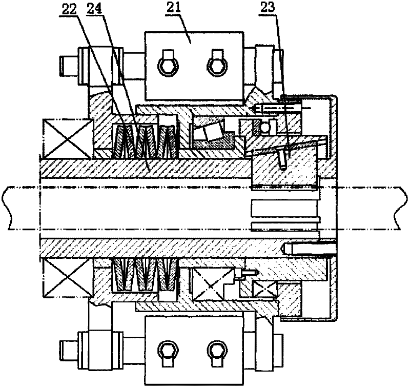
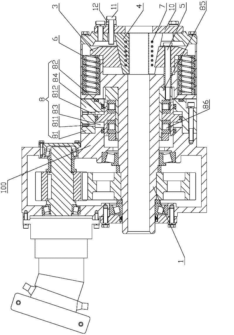
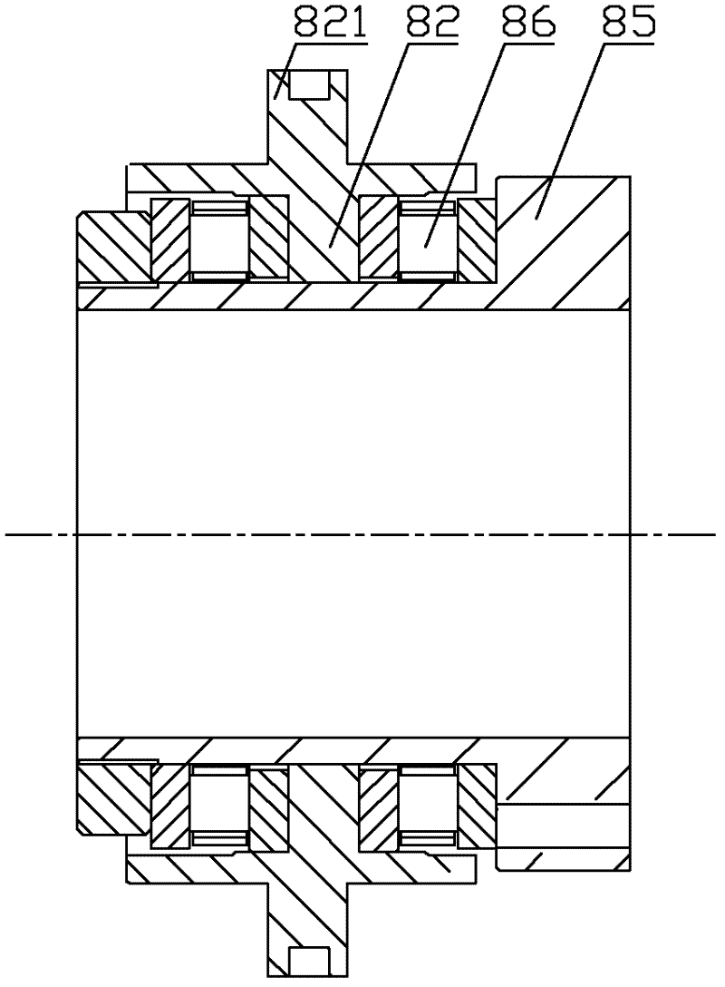
[0033] Please refer to Figure 2 to Figure 4 , figure 2 It is a structural schematic diagram of ...


PUM


Abstract

The invention discloses a tunnel drilling machine and a hydraulic power head device thereof. The hydraulic power head device is used for pushing a drill rod of the tunnel drilling machine, wherein a cylinder body of a hydraulic oil cylinder of the hydraulic power head device is fixedly connected with a power head main body; the cylinder body, the power head main body and a main shaft form a hydraulic oil cavity; the cylinder body is provided with a first oil liquid channel and a second oil liquid channel; a piston of the hydraulic oil cylinder is arranged inside the hydraulic oil cavity and is provided with a bulge; the bulge, the cylinder body and the power head main body form a first oil cavity and a second oil cavity; the first oil liquid channel is communicated with the first oil cavity; and the second oil liquid channel is communicated with the second oil cavity. When a slip bowl acts on a slip, hydraulic pressure compensation is applied to the hydraulic oil cylinder except that the main shaft acts on the slip bowl, so that the slip clamps or loosens the drill rod through a more flexible response, and the tunnel drilling machine has higher working efficiency. Simultaneously, the hydraulic oil cavity surrounds the main shaft, and the oil supply or the oil leakage of the hydraulic oil cavity is kept synchronous with each other, so that the possibility of unbalance loading of the main shaft is greatly reduced, and the safe and reliable properties of a hydraulic power head are improved.

Description

technical field [0001] The invention relates to the technical field of tunnel drilling machines, in particular to a hydraulic power head device for tunnel drilling machines. In addition, the present invention also relates to a tunnel drilling machine comprising the above-mentioned hydraulic power head device. Background technique [0002] The hydraulic power head device is an important part of the fixed tunnel drilling rig, which is mainly used to clamp the drill pipe of the tunnel drilling rig and drive it to rotate. At present, the power head of the full hydraulic drilling rig adopts a hydraulic motor as the power source, and drives the main shaft and the chuck to perform drilling after being decelerated by the reduction box. [0003] Commonly used chucks have the following forms: 1. Spring force clamping, hydraulic pressure release (normally closed); 2. Hydraulic pressure clamping, spring force release (normally open); 3. Hydraulic pressure clamping , the hydraulic pres...

Claims


Application Information

Patent Timeline
IPC IPC(8): E21B3/02E21B19/10
Inventor 徐延国李延富王平计展陈涛
Owner SANY HEAVY EQUIP
Why Eureka
Try Eureka