Device for mounting and take-down mould covering device of rotation cutting anvil cylinder

A rotary cutting, cylinder technology, applied in the direction of manufacturing tools, metal processing, metal processing equipment, etc., can solve problems such as decreased machine productivity, large covering strips, consumption, etc.

Inactive Publication Date: 2002-11-27
MARTIN SA
View PDF0 Cites 8 Cited by
  • Summary
  • Abstract
  • Description
  • Claims
  • Application Information

AI Technical Summary

Problems solved by technology

Due to the high productivity of rotary die-cutting machines, this operation has to be repeated frequently, and besides causing a decrease in machine productivity, it also consumes a large amount of covering strips

Method used


Image

  • Device for mounting and take-down mould covering device of rotation cutting anvil cylinder
  • Device for mounting and take-down mould covering device of rotation cutting anvil cylinder
  • Device for mounting and take-down mould covering device of rotation cutting anvil cylinder

Examples


Embodiment Construction

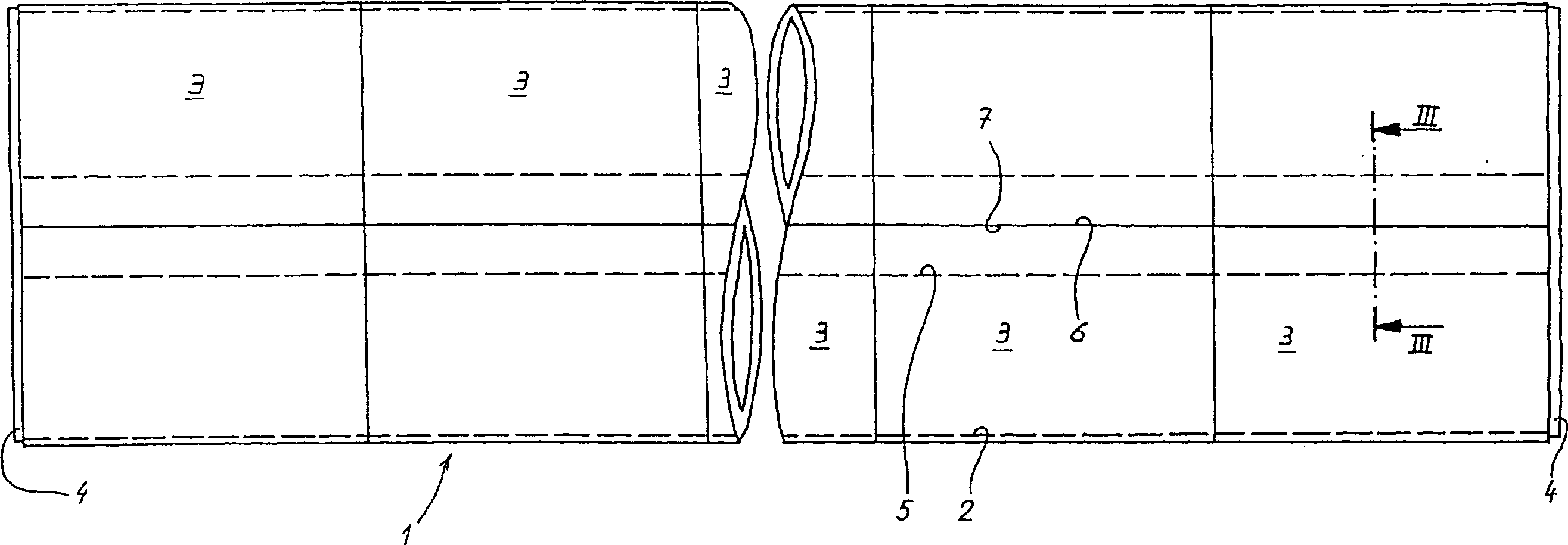
[0022] figure 1 Is a schematic view of a rotary cutting anvil cylinder 1 comprising a cylinder 2 on which covering strips 3 are wound and held at each end by stop discs 4. The cylinder 2 has a groove 5 extending over its entire length. The ends 6, 7 of the covering strip 3 fit into a locking and unlocking device 8 (see image 3 , 4 and 5) within the fastening and loosening device.

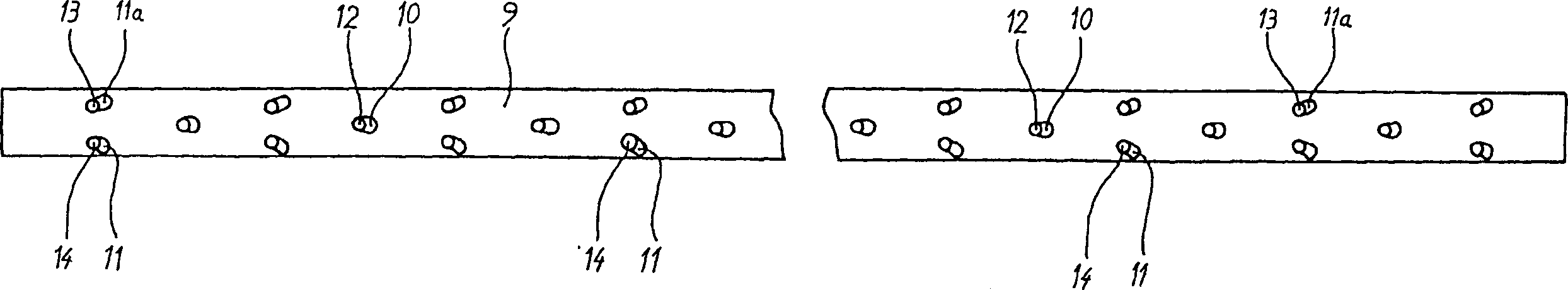
[0023] figure 2 is a plan view of a removable slide 9 used in the locking and unlocking device 8 . The removable slide 9 comprises a guide groove 10 and a groove 11 in the shape of a linear cam in which rollers 12, 13 and 14 fit (see Figures 3 to 6 ).

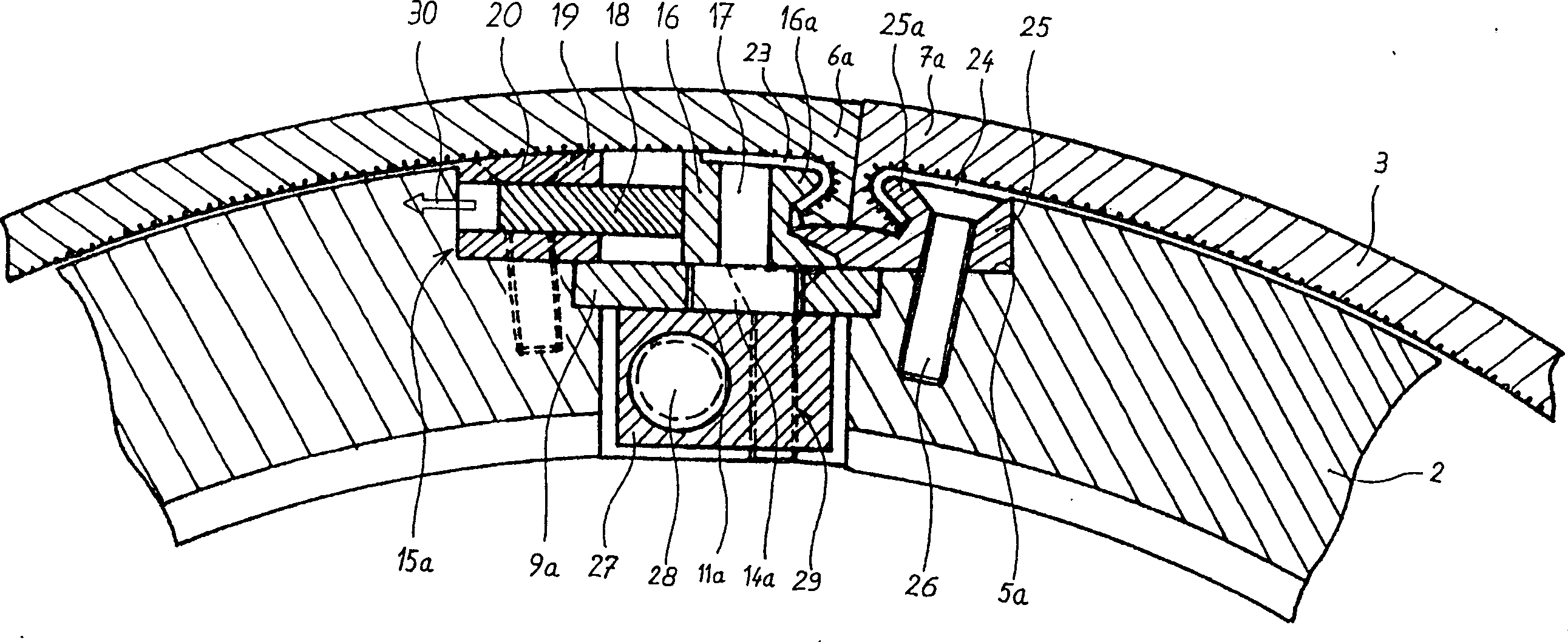
[0024] image 3 is along figure 1 Partially cutaway view taken along the line III-III, which shows a locking and unlocking device 15a in which only one pawl 16 is in the fastening position of the covering strip 3. The locking and unlocking device 15a comprises a removable slide 9a comprising grooves 11a in the shape of linear cams in which...


PUM


Abstract

The fastening / dismantling system consists of locking elements for the ends of the counter-cutting cylinder covering strips, each comprising a locking assembly fitting into a slot (5) in the outer edge of the cylinder (2) and incorporating a mobile slider (9) with guide slots (10) and cam slots (11, 11a) engaging with rollers on a jaw gripping one end of the covering strip. The slider is operated by a traction assembly (44) with a screw (49) interacting with a nut (55) fixed to the bottom of the slider.

Description

(1) Technical field [0001] The invention relates to a device for mounting and removing a die cover of a rotary cutting anvil cylinder. (2) Background technology [0002] The operation of rotary die cutting of cardboard or corrugated cardboard is well known, employing devices, in particular on the one hand, using a tool holding cylinder consisting of a metal cylinder on which is fixed There is a housing, preferably made of wood, into which a metal cutting ruler is inserted, and on the other hand a cutting anvil cylinder, usually called an anvil, is used. The anvil cylinder consists of a metal cylinder to which a cover strip, typically of plastic such as polyurethane, is mounted. [0003] The tool holding cylinder is covered by a housing with a variety of cutting ruler configurations according to the shape and size of the box to be cut. For corrugated board, the material to be cut passes between the tool holding cylinder and the cutting anvil cylinder, while the die cutting ...

Claims


Application Information

Patent Timeline
Patent Type & Authority Applications(China)
IPC IPC(8): B26F1/44B23P19/00B26D7/20B26F1/38
CPCB26D7/20B26D2007/202Y10T29/49558Y10T83/089Y10T83/606Y10T83/9466B23P19/00
Inventor B·卡德博斯克
Owner MARTIN SA
Why Eureka
Try Eureka