Heat exchanger

A technology for heat exchangers and heat-insulating containers, which is applied to heat exchange equipment, heat exchanger shells, lighting and heating equipment, etc. It can solve the problems of increasing the position of piping, increasing the length of piping, and complicating piping. , to achieve the effect of reducing the insulation container, simplifying the piping, and reducing the cost

Inactive Publication Date: 2002-12-11
LINDE AG
View PDF1 Cites 0 Cited by
  • Summary
  • Abstract
  • Description
  • Claims
  • Application Information

AI Technical Summary

Problems solved by technology

This increases the pipe length necessary for pipe layout, increases t

Method used


Image

  • Heat exchanger
  • Heat exchanger

Examples


Embodiment Construction

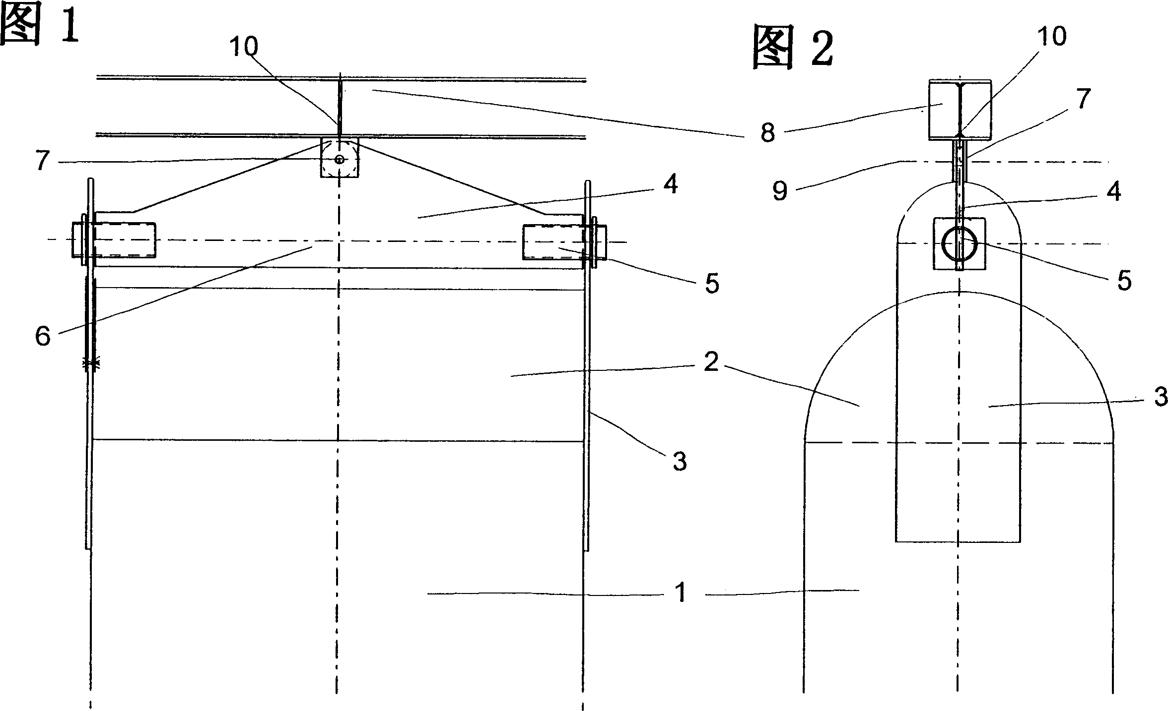
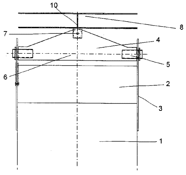
[0019] Figures 1 and 2 show the upper end of a heat exchange block 1 installed in the main heat exchanger of a cryogenic air separation plant. The overall main heat exchanger consists of a number of such heat exchange blocks 1 connected in parallel.

[0020] The heat exchange block 1 has a width of at most 240 mm. Arranged on the heat exchange block 1 is a collector-distributor 2 , the so-called header, from which one or more lines, not shown in detail, emerge.

[0021] Aluminum plates 3 are fastened to the heat exchange block 1 on two opposite sides, which protrude upwards beyond the headers 2 . A substantially triangular steel plate 4 or a steel beam designed according to statics requirements is placed perpendicular to the aluminum plate 3 above the header pipe 2 and hinged to the two aluminum plates 3 via pins 5 at two corners. The steel plate 4 can move relative to the heat exchange block 1 around the axis 6 formed by extending the two pins 5 .

[0022] On the third cor...


PUM


Abstract

The invention relates to a heat exchanger with at least one heat exchange block (1) and an insulating container surrounding the heat exchanger, wherein fastening means (3, 4, 5, 7) are provided for the heat exchange block ( 1) Suspended and fixed in an insulated container. According to the present invention, the heat exchange block (1) is movably arranged in the heat insulating container.

Description

technical field [0001] The invention relates to a heat exchanger having at least one heat exchange block and a heat insulating container surrounding the heat exchanger, wherein a fixing device is provided to suspend and fix the heat exchange block in the heat insulating container, and to the heat exchange block Use of exchangers in cryogenic air separation plants. Background technique [0002] In cryogenic air separation plants, the service air to be separated must be cooled to process temperature. This is usually achieved by indirect heat exchange of the use air with the product stream obtained in the air separation plant. In plants that process large volumes of air, the main heat exchanger is realized by several heat exchange blocks connected in parallel. In this case, the individual heat exchange blocks are usually designed as plate heat exchangers. [0003] The insulation of the main heat exchanger is achieved by enclosing the heat exchanger in a thermally insulated c...

Claims


Application Information

Patent Timeline
IPC IPC(8): F28F9/00F25J3/00F25J3/04
CPCF25J3/04945F25J5/002F25J2290/42F25J3/04
Inventor 斯特凡·威廉沃尔夫冈·贝德尔
Owner LINDE AG
Why Eureka
Try Eureka