
Driver for tyre homogeneity testing instrument

A driving device, uniformity technology, applied in the direction of automobile tire testing, measuring device, work drive, etc., can solve the problem of increasing time and so on

Inactive Publication Date: 2002-12-11
AKRON SPECIAL MACHINERY
View PDF0 Cites 9 Cited by
  • Summary
  • Abstract
  • Description
  • Claims
  • Application Information

AI Technical Summary

Problems solved by technology

In most prior art systems, machining errors and the additional inertia of these components increase the time required to reverse the motor and change the tire or load wheel steering

Method used


Image

  • Driver for tyre homogeneity testing instrument
  • Driver for tyre homogeneity testing instrument
  • Driver for tyre homogeneity testing instrument

Examples


Embodiment Construction

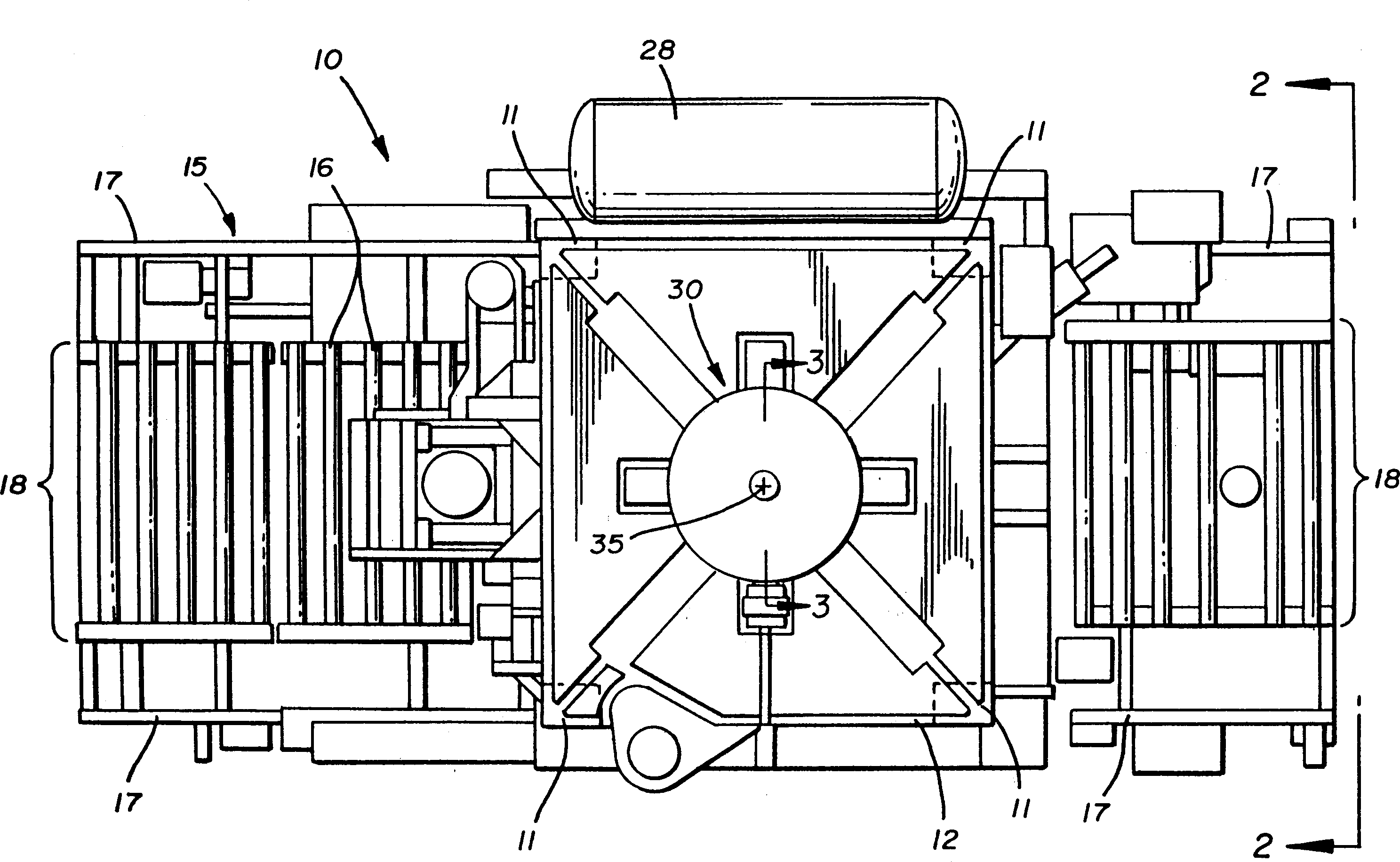
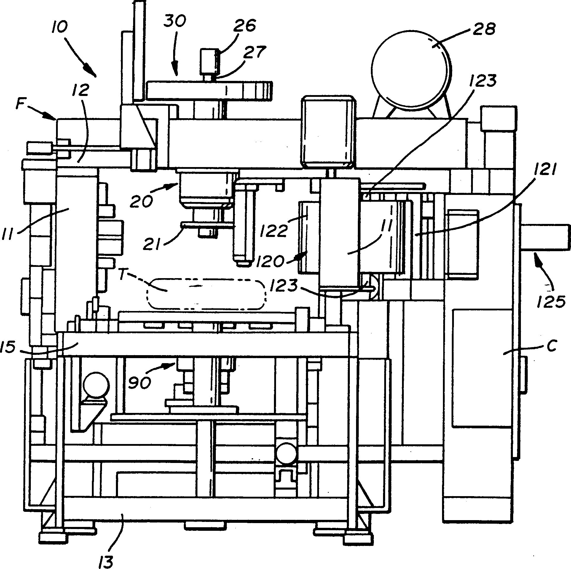
[0016] from figure 1 As can be seen, the tire uniformity testing machine 10 generally includes vertical side frame members 11 , generally horizontal top frame members 12 , and generally horizontal bottom frame members 13 , which form the frame F of the testing machine 10 . The frame members 11, 12, 13 form a generally box-like structure in which the tire T is placed and tested.

[0017] figure 1 As clearly shown, the tires T may be fed into and withdrawn from the frame F of the testing machine 10 by means of a conveyor 15 which may comprise a plurality of rollers 16 rotatably supported on parallel side beams In the middle of 17, a roller table is formed. The side beams 17, 17 of the conveyor 15 and the side frame members 11, 11 of the testing machine 10 are generally spaced apart to accommodate tires of various diameters. Once the tire T enters the frame F of the testing machine 10, the tire T is Clipped and ready to test.

[0018] To briefly illustrate this again, the upp...


PUM


Abstract

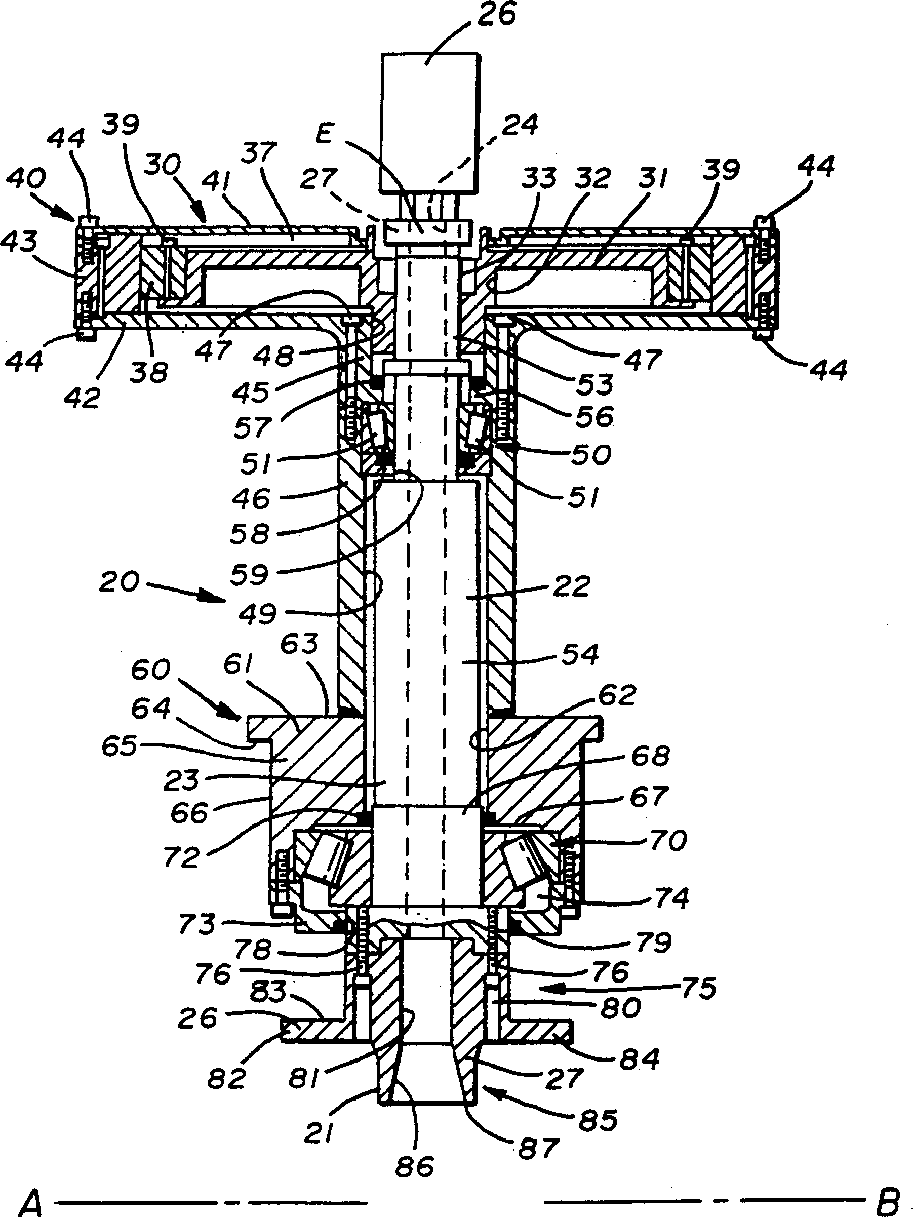
A tire uniformity testing machine having a frame for receiving a tire to be tested, a rotatable chuck located in the frame, and a spindle directly driven by a motor connected to the spindle so that the tire is clamped It is held in the chuck assembly and rotated by the motor. The motor is arranged axially aligned with the mandrel.

Description

technical field [0001] The present invention generally relates to tire uniformity testing machines. More particularly the present invention relates to drive means for tire uniformity testing machines. Most particularly, the present invention relates to a spindle drive for a tire uniformity testing machine. Background technique [0002] Usually, tire uniformity testing machines are used to test the performance of tires after they are manufactured. This test consists of measuring the dimensional properties of the tire and the forces acting on the tire under varying loads. To perform the load test, the tire is loaded onto the chuck of the tire uniformity tester, inflated and rotated by a drive unit connected to the chuck spindle, with the loading wheel in contact with the periphery of the tire. [0003] Previously, the electric motors for these drives were mounted on tire uniformity testing machines at a distance from the spindle on which the loading wheels or chucks were mo...

Claims


Application Information

Patent Timeline
Patent Type & Authority Applications(China)
IPC IPC(8): G01M1/16B60C19/00G01M17/02
CPCG01M17/022Y10T82/16967Y10T82/25Y10T82/26G01M17/02
Inventor D·老波林R·L·德尔莫罗D·P·克劳斯
Owner AKRON SPECIAL MACHINERY
Learn More