Relay protection device

A relay protection device and relay technology, which is applied in the direction of circuit devices, emergency protection circuit devices, emergency protection devices with automatic disconnection, etc., can solve the problems of discrimination, inaccurate direction discrimination, instability, etc.

Inactive Publication Date: 2003-03-12
KK TOSHIBA
View PDF0 Cites 6 Cited by
  • Summary
  • Abstract
  • Description
  • Claims
  • Application Information

AI Technical Summary

Problems solved by technology

[0016] However, in the system surge, there is a problem that it is difficult to use the above-mentioned polar quantity direction discrimination element to discriminate the fault.
This is because the magnitude of the system voltage and current, and the phase slip change due to the existence of the surge phenomenon. In terms of direction discrimination, it is necessary to use the necessary polarity as a fixed value, but there is instability, so the direction cannot be accurately determined. Discrimination's sake

Method used


Image

  • Relay protection device
  • Relay protection device
  • Relay protection device

Examples


no. 1 Embodiment

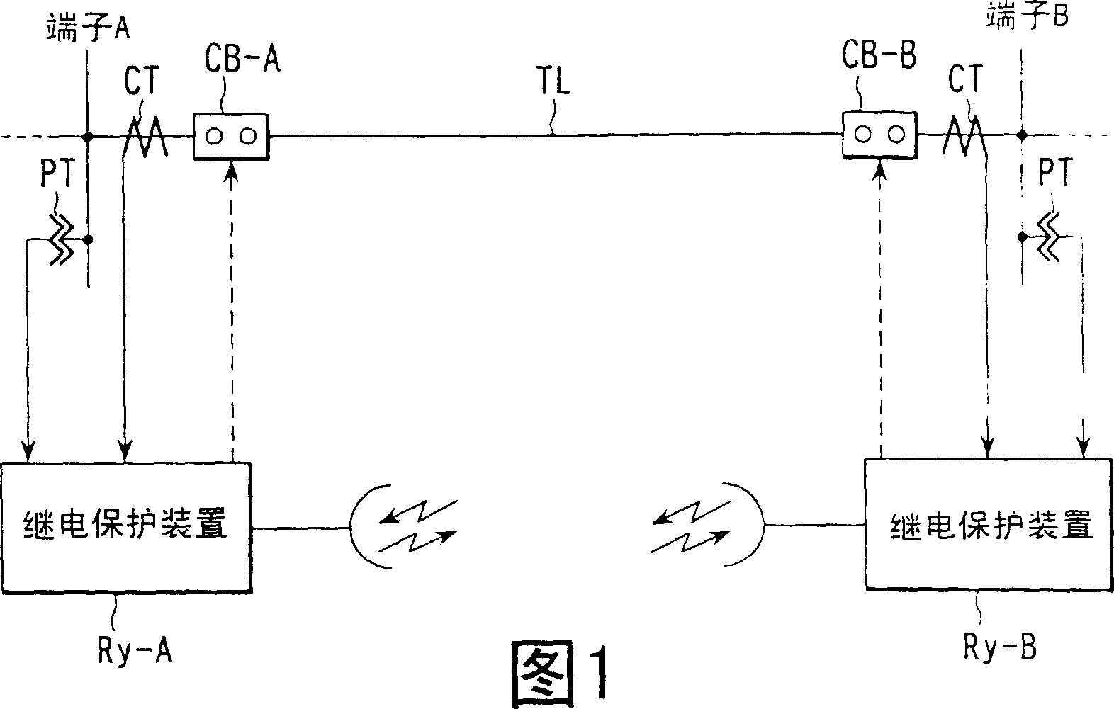
[0126] Referring to Figure 1 and figure 2 The first embodiment will be described.

[0127] First, in FIG. 1 , TL is a transmission line to be protected between the A terminal and the B terminal connecting the power system. The relay protection device R that extracts the current (I) and voltage (II) through the current transformer CT and the voltage transformer to perform protection calculations is installed on the A terminal and the B terminal respectively. y -A and R y -B.

[0128] Since the two relay protection devices R y -A, R y -B has the same structure, so the relay protection device R y -A represents their internal structure.

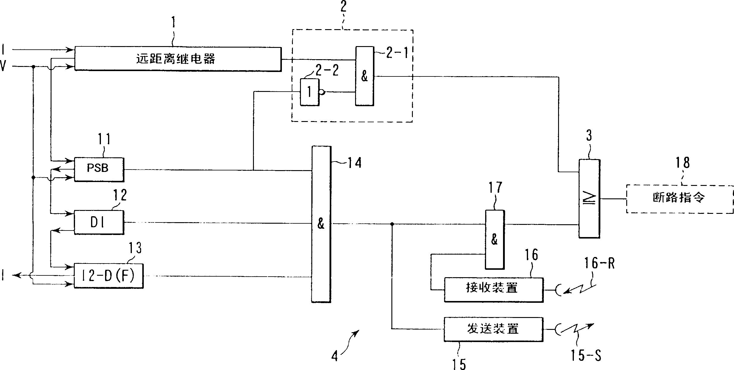
[0129] figure 2 is the relay protection device R in Figure 1 y -A detailed structure diagram.

[0130] 1 is a long-distance relay for main protection. The remote relay 1 performs a distance measurement calculation based on the voltage and current extracted from the terminal A, and operates when the obtained distance measurement impeda...

no. 2 Embodiment

[0148] Next, refer to Figure 4 The second embodiment will be described. In addition, the same reference numerals are assigned to the same parts as the already described relays and logic circuits, and descriptions thereof are omitted.

[0149] Figure 4 and figure 2 The difference is that: Figure 4 will be figure 2 The detection relay 12 of the current change part is replaced by a failure detection circuit 20 represented by a dotted line frame. Since the other components are the same as those described above, only the fault detection circuit 20 will be introduced here.

[0150] 21 is an undervoltage relay (abbreviated as UV in the figure), and it works when the voltage is less than a stable value because of a failure at the nearest end. Only one is shown here, and in practical application, it is desirable to set the phase voltage UV for detecting a ground fault and the line voltage UV for detecting a short circuit fault.

[0151] 22 is a zero-phase overcurrent relay ...

no. 3 Embodiment

[0156] Refer below Figure 5 The third embodiment will be described. In addition, for the relays already described, the same parts of the logic circuit are attached with the same symbols and their explanations are omitted.

[0157] This embodiment is to figure 2 circuit for fault detection relays with Figure 4 The fault detection relay is combined. If it is this embodiment, because among the four relays of the zero-phase overcurrent relay 22, the reverse phase overcurrent relay 23, the circuit change part detection relay 12 and the undervoltage relay 24, no matter which one works, the system failure can be detected , so the fault detection accuracy can be improved.


PUM


Abstract

In a protective relay system according to an aspect of the present invention, a direction of a fault is correctly determined during system oscillation using one of a negative-phase-sequence relay and a zero-phase-sequence relay. A circuit breaker is tripped only when an internal fault is determined at both terminals to be protected using a carrier signal. Thus, even though a fault occurs during system oscillation, the circuit breaker can be tripped against the internal fault.

Description

technical field [0001] The invention relates to a relay protection device, which can remove the occurrence point of the fault and protect the system when a fault occurs in a system surge. Background technique [0002] refer to Figure 17 Introduce the traditional relay protection device. [0003] Figure 17 It shows the relationship between the existence domain (load area) of the ranging impedance Z caused by the power flow and the fault direction detection element (mho characteristic, ohm characteristic) under the normal load state of the power system. In such a healthy load state, the region where the ranging impedance of the power flow exists (load range) is often located away from the operating region of the fault direction detection element (mho characteristic, ohmic characteristic). Therefore, the mho relay and the blinder relay do not need to perform unnecessary fault detection. [0004] However, when the power flow of the power system increases, the ranging impedan...

Claims


Application Information

Patent Timeline
Patent Type & Authority Applications(China)
IPC IPC(8): H02H3/26H02H3/08H02H3/38H02H3/40H02H3/48H02H7/26
CPCH02H7/261H02H3/40H02H3/081H02H3/26
Inventor 加濑高弘天羽秀也园部泰孝
Owner KK TOSHIBA
Why Eureka
Try Eureka