Railroad utilized unloading equipment by using hydraulic force to careen tracks

A track and hydraulic technology, which is applied in the field of railway hydraulic tilting track unloading equipment, can solve the problems of large floor area, many auxiliary facilities, and inconvenient use

Inactive Publication Date: 2003-05-07
黄祖文
View PDF0 Cites 3 Cited by
  • Summary
  • Abstract
  • Description
  • Claims
  • Application Information

AI Technical Summary

Problems solved by technology

Another way is to use a dumper to unload the car. In this way, only one car can be unloaded at a time, and many auxiliary facilities are required...

Method used


Image

  • Railroad utilized unloading equipment by using hydraulic force to careen tracks
  • Railroad utilized unloading equipment by using hydraulic force to careen tracks
  • Railroad utilized unloading equipment by using hydraulic force to careen tracks

Examples


Embodiment Construction

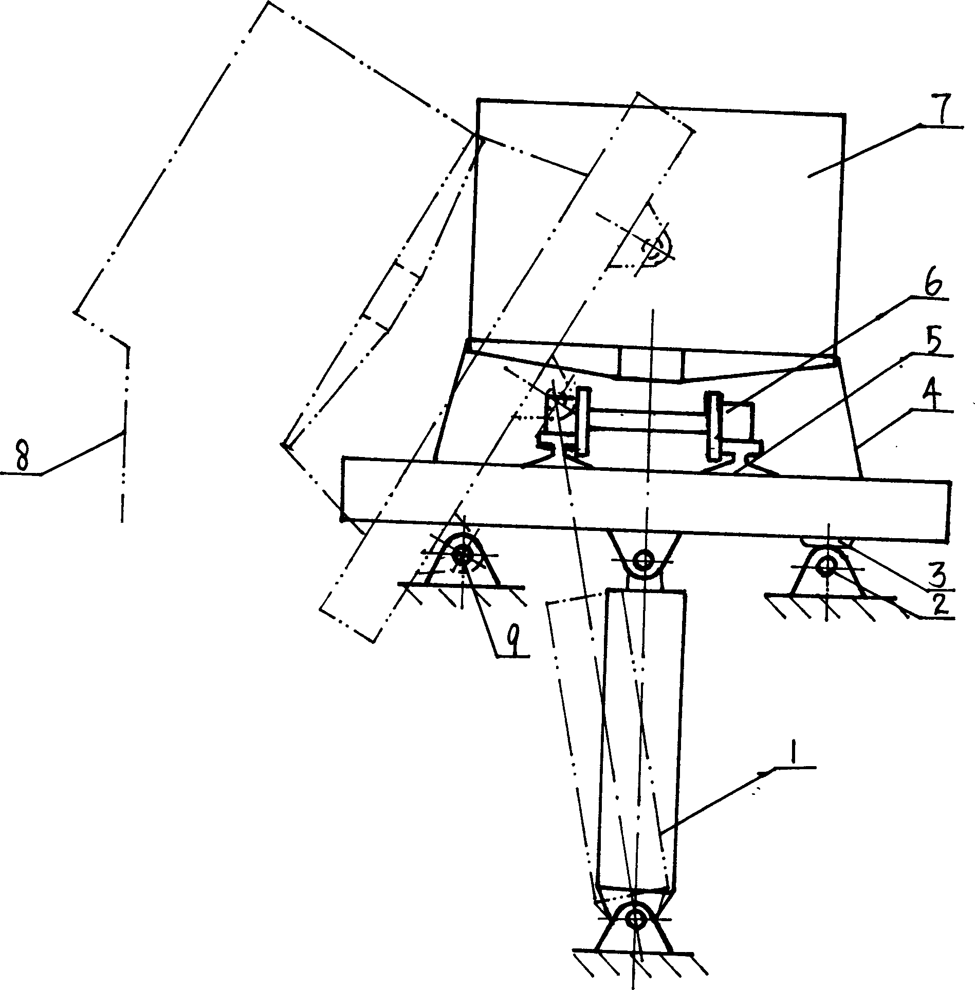
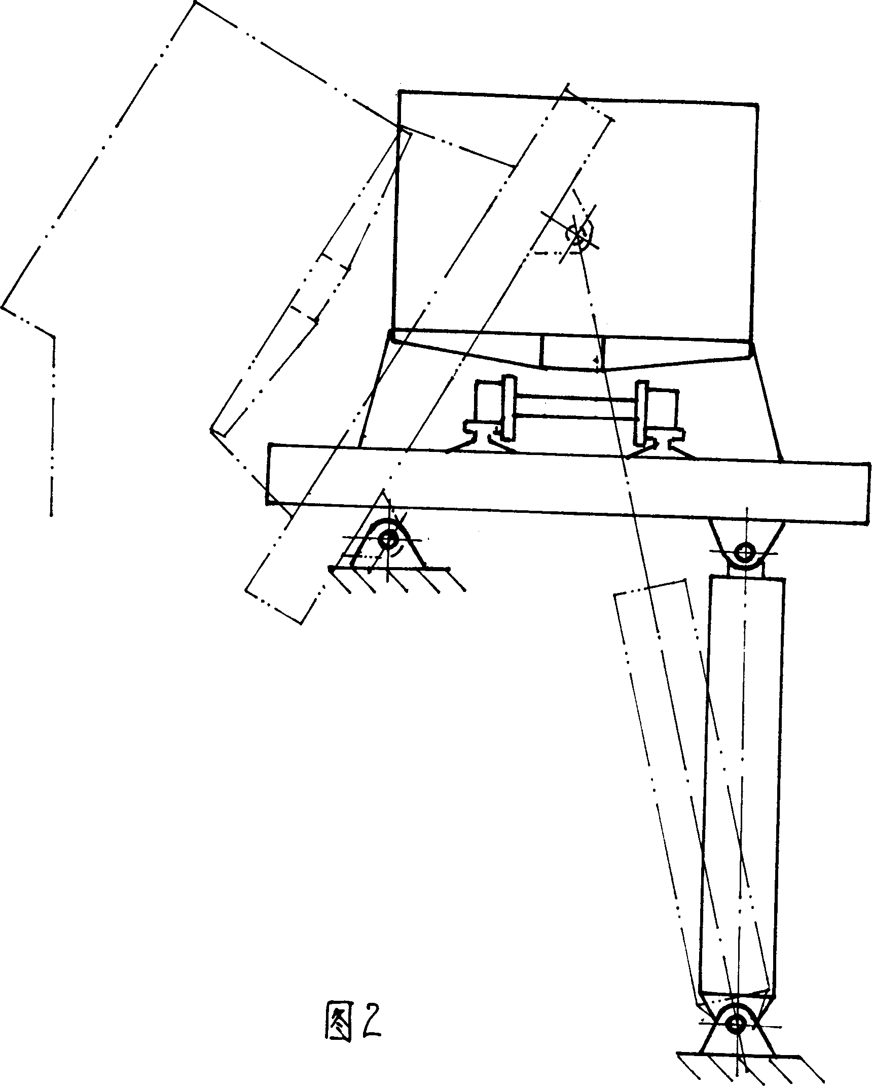
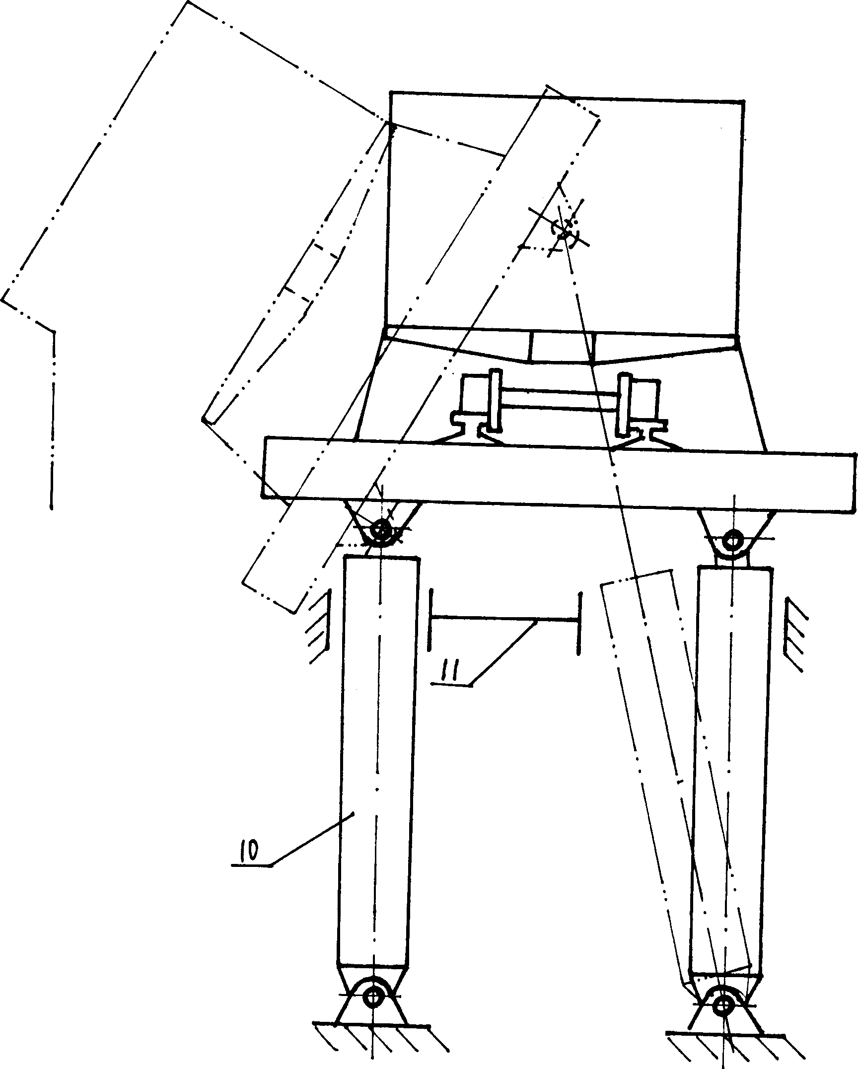
[0015] The present invention includes a hydraulic cylinder 1, a base 2, a bayonet pin 3, a safety fastening device 4, a track support 5, a wheel 6, a carriage 7, a baffle 8, a hinge shaft 9, an oil cylinder 10, a restricting device 11, and an ejection piston 12. Roller 13, ejector rod 14, track 15, booster frame 16, pillar 17.

[0016] The track support 5 of its track part is hinged with the base 2 on one side, and the track support 5 is connected with the lifting device that jacks up the track support 5 to make it rotate around the base 2. Safety fastening device 4.

[0017] The lifting device is provided with at least one ejected hydraulic cylinder 1 below the track support 5 , the hydraulic cylinder 1 is hinged to the track support 5 , and one end of the track support 5 is hinged to the base 2 .

[0018] Described hydraulic cylinder 1 is supported on the middle part of track support 5, and one end of track support 5 is hinged with base 2, as attached figure 1 As shown, in...


PUM


Abstract

An unloading mechaniwm which hydraulically tilted rails for ailway car is composed of rail supporter pivoted to base, high-safety fasteners on the rail supporter for fastening the rail way car, and lifting unit linked to the rail supporter for tilting it. The said lifting unit is hydraulic cylinder with lifting member. Its advantages are simple structure and short unloading time.

Description

technical field [0001] The invention relates to a railway hydraulic tilting track unloading equipment for unloading railway carriages. Background technique [0002] One of the mechanized unloading methods for railway transportation is a pneumatic or hydraulic dump truck, which uses a cylinder on the side of the carriage to tilt the carriage to one side for unloading in a special carriage. This method must be a special carriage. side dump truck. Another way is to use a dumper to unload the car. In this way, only one car can be unloaded at a time, and many auxiliary facilities are required, such as belt conveyors, locomotives for pushing and pulling out, etc., and the structure is complex and the floor space is large. Inconvenient to use. Contents of the invention [0003] The object of the present invention is to provide a kind of hydraulic rolling track unloading equipment for railways which is simple in structure, can be t...

Claims


Application Information

Patent Timeline
IPC IPC(8): B65G67/46
Inventor 黄祖文
Owner 黄祖文
Why Eureka
Try Eureka