Multifunctional massage traction table

A traction bed, multi-functional technology, applied in the field of medical devices, can solve the problems of no massage function, inability to change orientation and angle at will, etc.

Inactive Publication Date: 2003-07-09
刘援朝
View PDF0 Cites 7 Cited by
  • Summary
  • Abstract
  • Description
  • Claims
  • Application Information

AI Technical Summary

Problems solved by technology

[0002] At present, the three-dimensional rotation of the traction bed used by doctors at home and abroad is graded, and the orientation and angle ca

Method used


Image

  • Multifunctional massage traction table
  • Multifunctional massage traction table
  • Multifunctional massage traction table

Examples


Embodiment Construction

[0008] The present invention will be further described below in conjunction with specific embodiments.

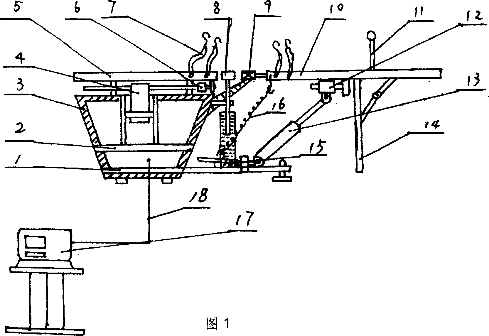
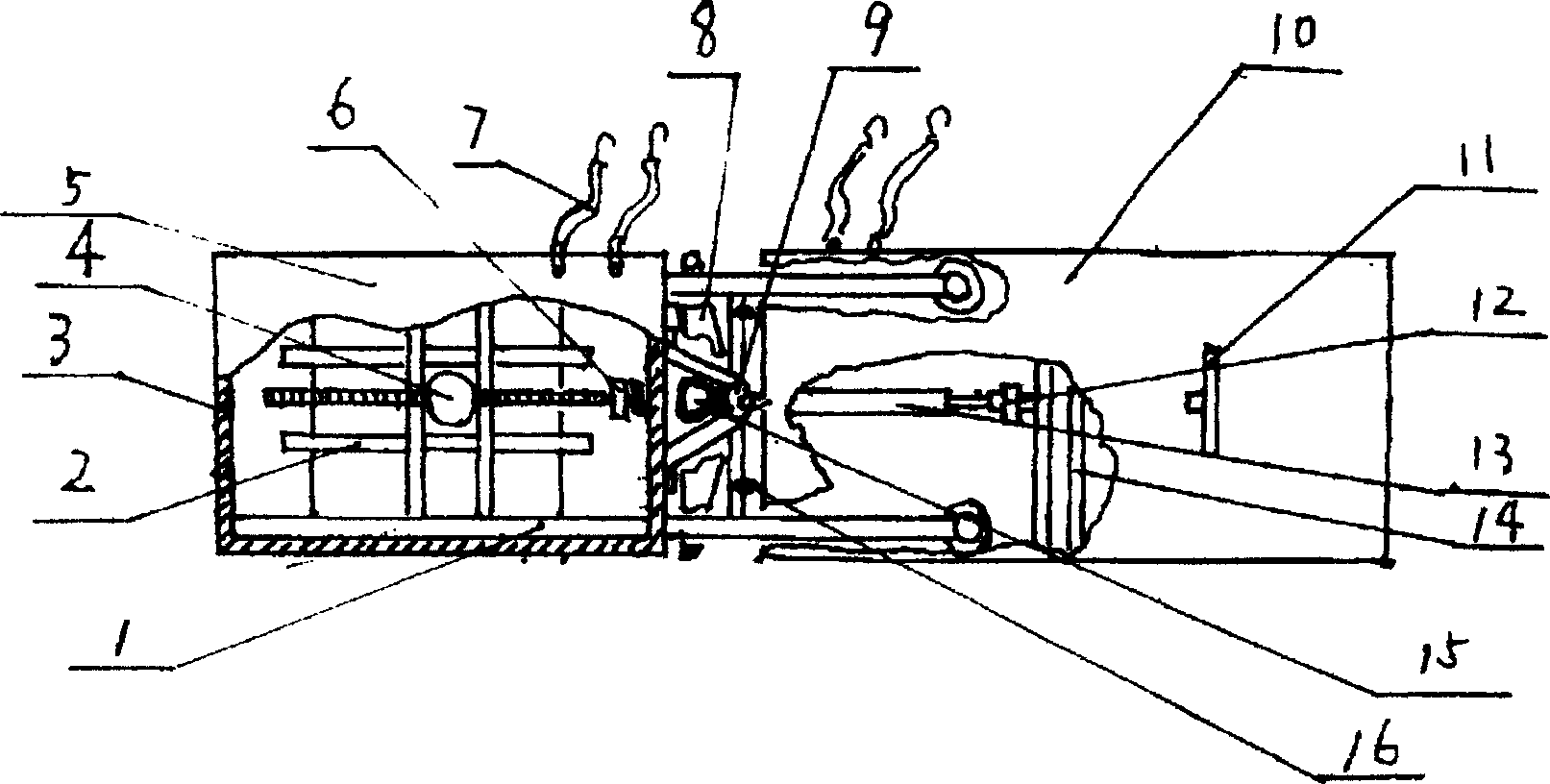
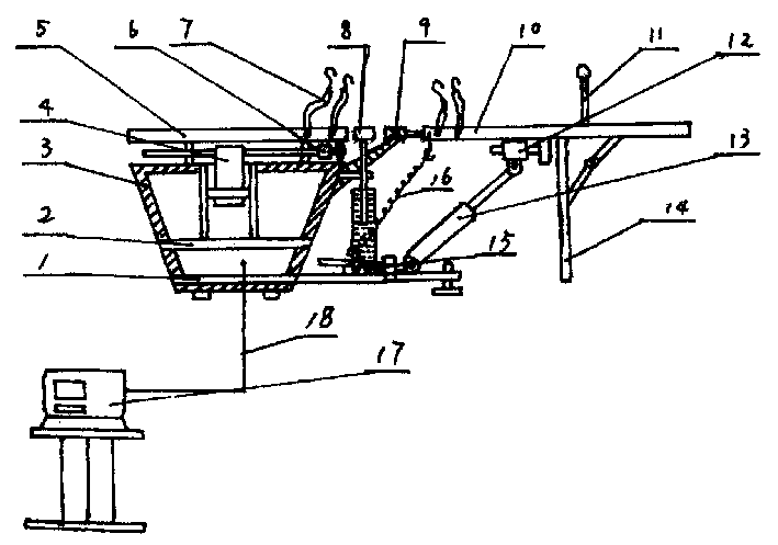
[0009] figure 1, figure 2 The multifunctional massage traction bed shown includes a control mechanism, a traction mechanism, a rotating mechanism, a massage board, and a support frame. The control mechanism is controlled by a microcomputer 11 via a control bus 18 according to a preset program. The support plate is divided into a back plate 5, a waist bridge 8 and three independent parts of the leg plate 10, the support frame is formed by connecting the bottom frame 1, the box shell 3, and the motor bracket 2, and the traction mechanism is a linear speed motor 4 installed on the motor bracket 2, and the linear motor The screw rod of 4 is fixedly connected to the back plate 5 through the pressure sensor 6, and the back plate 5 can slide left and right along the slideway on the box body 3. Both the back plate and the leg plate are composed of rotatable balls distributed on the...


PUM


Abstract

The multifunctional massage traction bed includes control mechanism, traction mechanism, turning mechanism, massage plate and support frame. The control mechanism utilizes microcomputer to control traction mechanism and display traction state. Said traction mechanism is fixed on the support frame, and can be fixedly-connected with back plate which can be horizontally moved along the slideway by means of pressure sensor. One end of the turning mechanism is fixed on the support frame, and its another end is connected with leg plate, the cranking handle bar fixed on the leg plate is turned, the leg palte can be freely stepless turned, the waist bridge is fixedly-connected with lifting device, and can be moved upward and downward.

Description

1. Technical field [0001] The invention relates to a medical device, in particular to a massage and traction bed. 2. Background technology [0002] At present, the three-dimensional rotation of the traction bed used by domestic and foreign doctors is graded, and the orientation and angle cannot be changed arbitrarily, and there is no massage function, which brings a lot of inconvenience to the doctor and the patient in the treatment process. 3. Contents of the invention [0003] The purpose of the present invention is to provide a traction bed, which is controlled by a microcomputer and displays the traction state, can perform stepless three-dimensional rotation, and can be used as a massage, which is conducive to promoting the cooperation between doctors and patients in the treatment process and improving the cure rate . [0004] In order to achieve the above object, the present invention includes a control mechanism, a traction mechanism, a rotating mechanism, a massage...

Claims


Application Information

Patent Timeline
IPC IPC(8): A61F5/042
Inventor 刘援朝
Owner 刘援朝
Why Eureka
Try Eureka