Spring cupport structure for reciprocating compressor

A reciprocating and compressor technology, applied in the field of spring support structures of reciprocating compressors, can solve the problems of lengthening of compressors and decreasing overall reliability of compressors, etc.

Inactive Publication Date: 2003-07-23
LG ELECTRONICS INC
View PDF0 Cites 13 Cited by
  • Summary
  • Abstract
  • Description
  • Claims
  • Application Information

AI Technical Summary

Problems solved by technology

That is: if figure 2 As shown, the front spring and the rear spring are arranged in a straight line with the rotor in between, the horizontal length (L) of the spring should be at least equal to the length of the front spring (L1) and the length of the rear spring (L2) And, this creates a problem that the length of the horizontal direction of the compressor is extended
[0013] In addition, both the front spring 51 and t

Method used


Image

  • Spring cupport structure for reciprocating compressor
  • Spring cupport structure for reciprocating compressor
  • Spring cupport structure for reciprocating compressor

Examples


Embodiment Construction

[0029] Reference will now be made in detail to the preferred embodiments of the invention, examples of which are illustrated in the accompanying drawings.

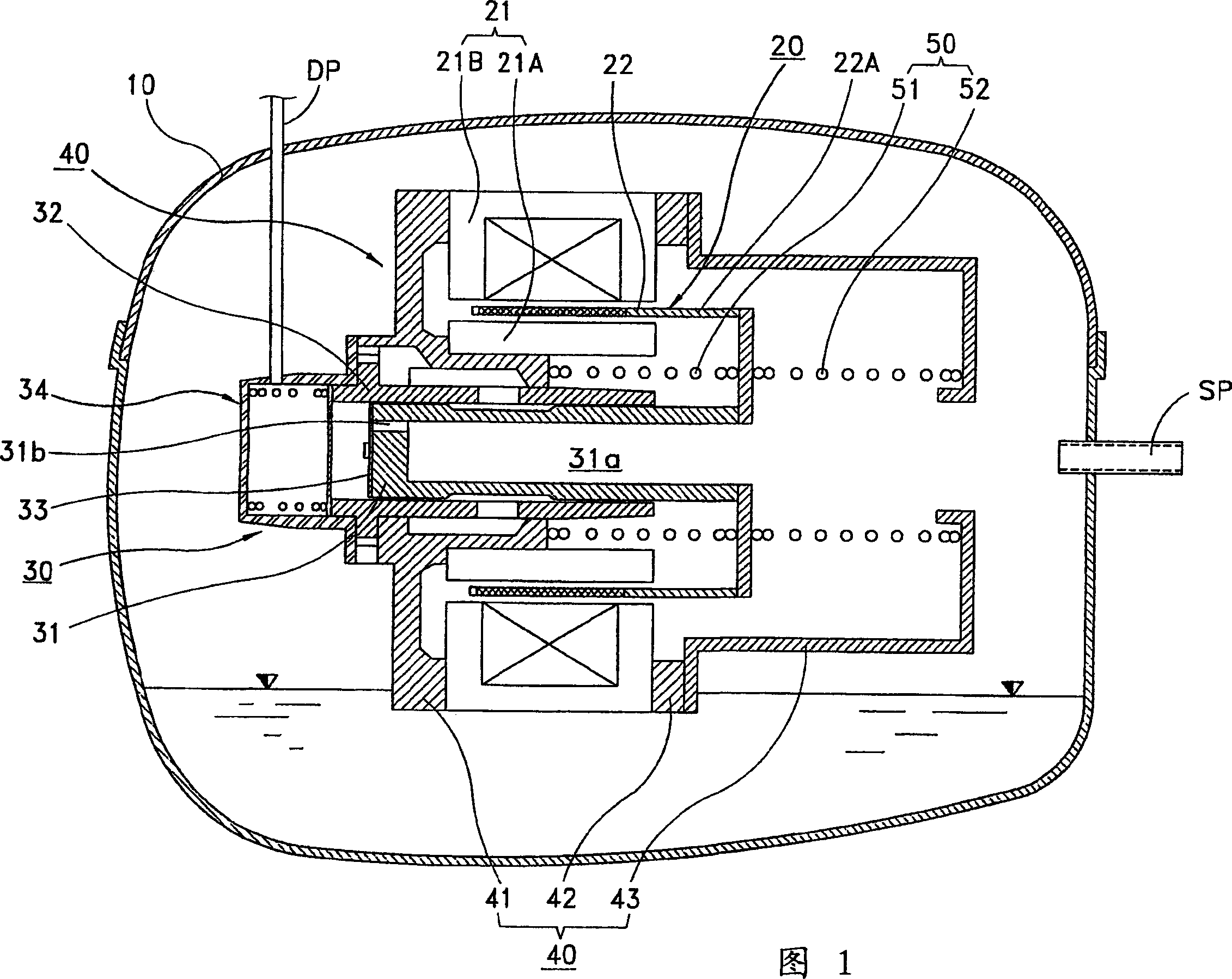
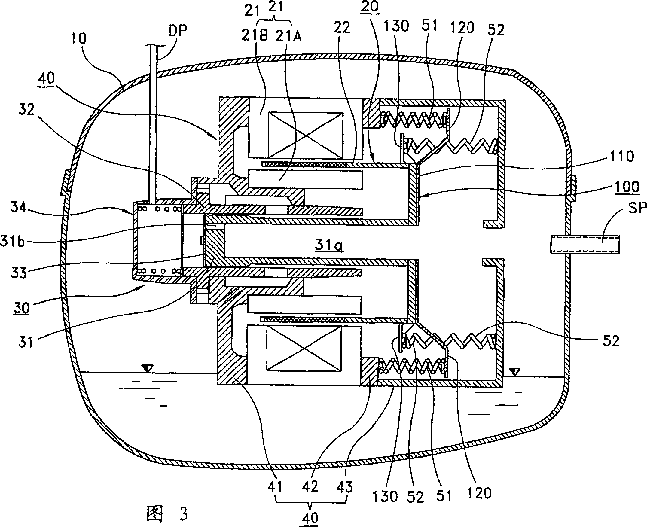
[0030] 3 is a vertical sectional view showing an example of a reciprocating compressor according to a preferred embodiment of the present invention; and Figure 4 is a vertical sectional view showing a state supported by a spring in a reciprocating compressor according to a preferred embodiment of the present invention.

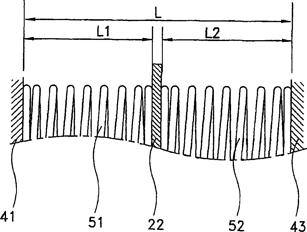
[0031] As shown in Figures 3 and 4, the spring support structure of the reciprocating compressor of the present invention includes: a spring support 100, which is fixed on the rotor 22 of the reciprocating motor 20 and combined with the rotor 22 so as to reciprocate with the rotor 22 On the joint portion (not shown) between the pistons 31; the front spring 51 and the rear spring 52 are respectively supported on both sides of the spring bracket and guide the reciprocating motion of the rotor 22 and the pis...


PUM


Abstract

A spring support (100) structure for reciprocating compressor having a frame unit (40) elastically supported inside a closed container (10); a reciprocating motor (20) fixed at the frame unit (40); a compression unit (30) having a piston (31) combined to an armature (22) of the reciprocating motor (20) and a cylinder (32) into which the piston (31) is slidably inserted to be fixed at the frame unit (40); and a spring unit (100) supporting a spring support (110) provided at the armature (22) or the piston (31) and guiding a reciprocal movement of the piston (31), wherein the spring unit (100) includes a plurality of front springs (51) supporting one side of the spring support (110) in parallel and a plurality of the rear springs (52) supporting the other side of the spring support. Since the front springs and the rear springs (52) elastically supporting both the armature (22) and the piston (31) are arranged in parallel to overlap with each other for a certain range, the horizontal length of the spring is reduced, resulting in that the compressor can be compact.

Description

technical field [0001] The invention relates to a spring supporting structure of a reciprocating compressor, in particular to a spring supporting structure of a reciprocating compressor used for elastically supporting the rotor of a reciprocating motor. Background technique [0002] Generally, a reciprocating compressor sucks in, compresses and discharges gas while a piston reciprocates within a cylinder. [0003] Fig. 1 is a vertical sectional view of a prior art reciprocating compressor [0004] As shown in Figure 1, a common reciprocating compressor includes a closed container 10, and in the container 10, the suction pipe (SP) and the discharge pipe (DP) are connected to each other; a reciprocating motor 20 fixed in the closed container 10 a compression unit 30 installed in the airtight container 10 and sucking, compressing and discharging gas; a frame unit 40 supporting the reciprocating motor 20 and the compression unit 30; and a spring unit 50 for elastically supporti...

Claims


Application Information

Patent Timeline
IPC IPC(8): F04B39/00F04B35/04
CPCF04B35/045F04B39/00
Inventor 宋桂永金正雨韩成周
Owner LG ELECTRONICS INC
Why Eureka
Try Eureka