Ink jet head
An inkjet head and ink technology, applied in printing and other directions, can solve problems such as damage to image quality
- Summary
- Abstract
- Description
- Claims
- Application Information
AI Technical Summary
Problems solved by technology
Method used
Image

Examples
Embodiment 1
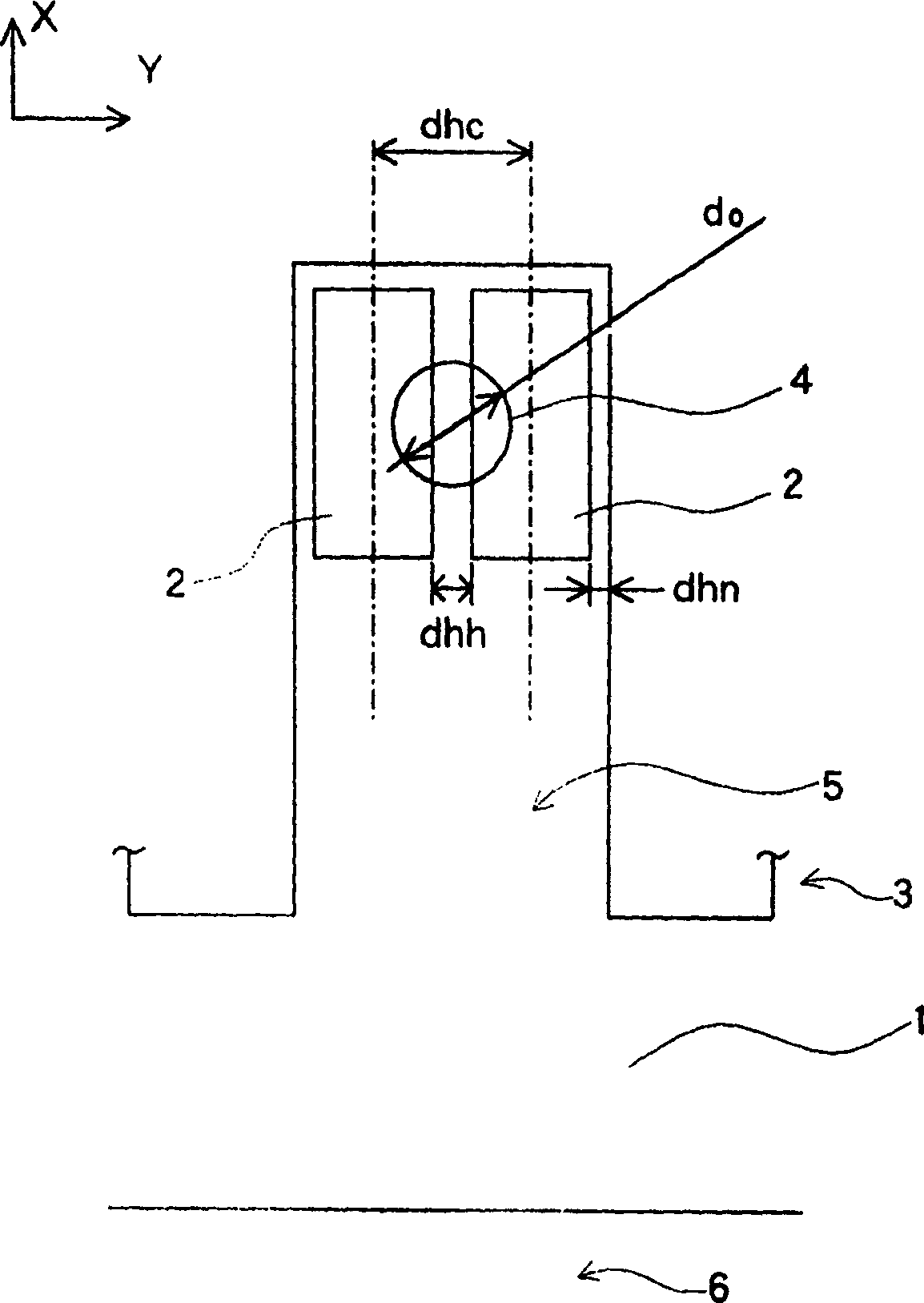
[0035] figure 1 It is a perspective plan view showing the arrangement relationship of the ink flow channel, the heating element, and the ejection port in the inkjet head according to the first embodiment of the present invention.
[0036] The inkjet head of this embodiment has a substrate 1 provided with a plurality of heating elements 2 on its surface, and a flow channel forming member 3 provided on the substrate 1 . The channel forming member 3 has a partition plate 3 a that separates the plurality of heating elements 2 two by two, and a top wall 3 b facing the substrate 1 . The partition plate 3 a forms a plurality of ink flow channels 5 for supplying ink to a pressure generating region constituted by the two separated heating elements 2 . In addition, in each ink channel 5, from the center of the pressure generating region constituted by the two heating elements 2, a ceiling wall 3b is formed on an extension line extending along the normal direction to the surface of the...
Embodiment 2
[0051] Figure 4A and 4B It is a figure showing the arrangement relationship of the ink flow channel, the heat generating body and the ejection port in the inkjet head of Example 2 of the present invention, Figure 4A is its top view, Figure 4B is its cross-sectional view.
[0052] Such as Figure 4A As shown, the inkjet head of this embodiment is provided with a pressure generating region of four heating elements 2 in one ink channel 5 . When the direction of the ink flow in the ink channel 5 is the X direction and the direction perpendicular thereto is the Y direction, two heat generating elements 2 are arranged in each of the X direction and the Y direction. In addition, these heating elements 2 are electrically connected in series by wiring. The ejection ports 4 are arranged on an extension line extending from the center of the pressure generating region formed by the four heating elements 2 along the normal direction to the surface of the pressure generating region....
Embodiment 3
[0059] Figure 5 It is a perspective plan view showing the arrangement relationship of the ink flow channel, the heating element, and the ejection port in the inkjet head according to the third embodiment of the present invention.
[0060] In the inkjet head of Example 3, as in Example 1, two elongated heating elements are arranged in one ink flow path 5 . Other configurations of the recording head are also the same as those in Example 1.
[0061] In this embodiment, the width of each heating element 2 is 11 μm, the length is 27 μm, the distance dhh between two heating elements 2 is 4 μm, and the distance dhc between the centers of two heating elements 2 is 15 μm. In addition, the opening diameter do of the discharge port 4 was 10.5 μm, and the height OH from the upper surface of the substrate 1 to the opening surface of the discharge port 4 was 40 μm.
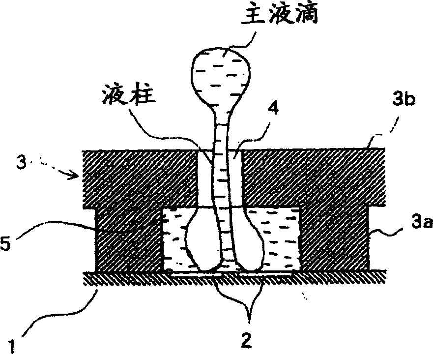
[0062] In this way, in the structure where the opening surface of the ejection port 4 is relatively far from the surface o...
PUM
 Abstract
Description
Claims
Application Information