Sewing machines

A technology of sewing machines and machine tables, which is applied in the field of sewing machines and can solve problems such as troublesome maintenance

Inactive Publication Date: 2003-11-19
JUKI CORP
View PDF0 Cites 7 Cited by
  • Summary
  • Abstract
  • Description
  • Claims
  • Application Information

AI Technical Summary

Problems solved by technology

Therefore, troublesome maintenance such as removing the lower cover 208, draining the lubricating oil 210 from the waste oil port 220 to the oil pan 207, and replacing the new lubricating oil 210 is necessary.

Method used


Image

  • Sewing machines
  • Sewing machines
  • Sewing machines

Examples


Embodiment Construction

[0026] Embodiments of the sewing machine of the present invention will be described below with reference to the accompanying drawings.

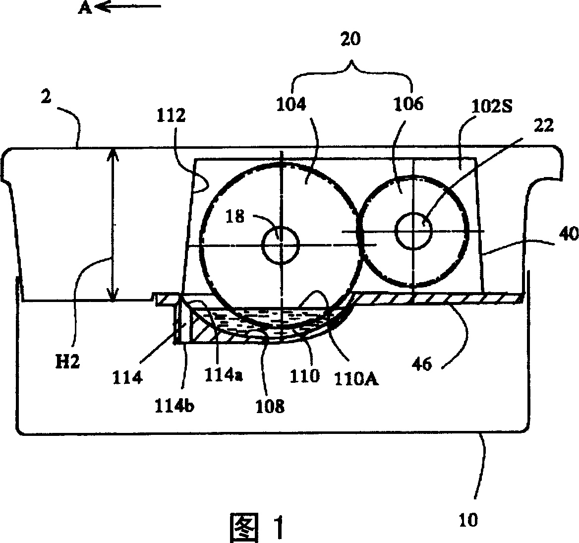
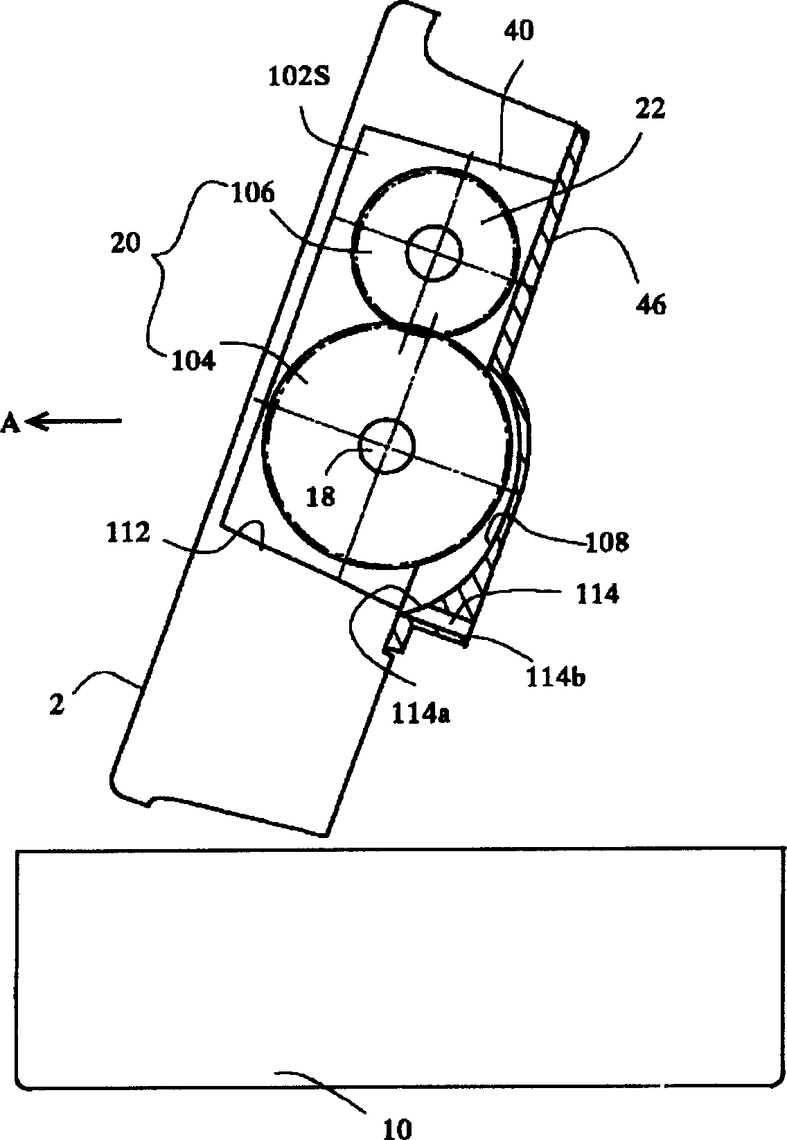
[0027] First, refer to Figure 7 and Figure 8 The schematic structure of the sewing machine of this invention is demonstrated. This sewing machine 1 is a zigzag stitch sewing machine that can move in a direction perpendicular to the conveying direction of the object to be sewn by an unillustrated swinging needle mechanism that swings the needle bar 3, and has a base portion 2 and a slave base portion 2. Upright nose 4. The base unit 2 is composed of a main base unit 6 and a cylindrical base unit 8 that is elongated compared with the main unit base portion 6 . The oil pan 10 is arranged below the main body table portion 6 , and the hook cover 12 is arranged below the cylindrical table portion 8 . The hook cover 12 can be opened and closed with respect to the bottom plate 2 .

[0028] The rotation of the upper shaft 14 is rotationally dri...


PUM


Abstract

The invention provides a sewing machine which gets lubricants ejected into an oil pan to leave none thereof in a gear box when the sewing machine is levelled. In the sewing machine which is provided with a bed part 2, the oil pan 10 arranged below the bed part and a gear box 40 which is arranged within the bed part while housing a gear device 20 for transmitting driving forces of the lower shaft 18 to a hook drive shaft 22 and in which the gear box has an under cover 46 with a waste oil port 114 that is so formed as to let the lubricant 110 be ejected within the gear box to the oil pan 10, the waste oil port has an upper opening 114a bored into the gear box 40 and a lower opening 114b bored toward the side of the oil pan 10, the upper opening 114a of the waste oil port 114 is so positioned as to be higher than the lowest part of a space 102S within the gear box 40 when the sewing machine is standing while being down to the lowest of the space within the gear box when it is leveled.

Description

technical field [0001] In particular, the present invention relates to a sewing machine including a gear box provided with a waste oil port for discharging lubricating oil to an oil pan. Background technique [0002] Conventional sewing machines such as Figure 10 and 11 As shown, there are: a machine part 202 with a sewing machine head (not shown) erected above, an oil pan 207 arranged below the machine part 202, and a housing for transmitting the driving force of the lower shaft 203 to the rotary hook driving shaft 205. The space part 206S of the gear unit 204 and the gear box 206 formed by opening the lower part of the machine part 202. The gear unit 204 is composed of a large gear 212 fixed to the lower shaft 203 and a small gear 214 fixed to the hook drive shaft 205 . Lubricating oil (not shown) for supplying oil to the rotary hook and the like is stored in the oil pan 207 . [0003] In addition, since the gears 212, 214 of the gear unit 204 are engaged at a high spe...

Claims


Application Information

Patent Timeline
Patent Type & Authority Applications(China)
IPC IPC(8): D05B71/00D05B73/04
Inventor 小池秀彦
Owner JUKI CORP
Why Eureka
Try Eureka