Multicasting messag transmission method base on two layer exchange device

A layer-2 switching device and multicast message technology, which is applied in store-and-forward switching systems, electrical components, transmission systems, etc., can solve the problem of wasting network resources and achieve the effect of avoiding the waste of network resources

Inactive Publication Date: 2003-11-26
HUAWEI TECH CO LTD
View PDF0 Cites 39 Cited by
  • Summary
  • Abstract
  • Description
  • Claims
  • Application Information

AI Technical Summary

Problems solved by technology

When LANSWITCH generates a Layer 2 forwarding table about the multicast MAC address, its VLAN ID uses the VLAN ID of the access port on the user side that received the IGMP message. For data packets (actually, the sources of multicast programs are all on the network side, and the multicast data packets are all sent from the uplink port of LANSWITCH), LANSWITCH will add a VLAN header composed of the VLAN

Method used


Image

  • Multicasting messag transmission method base on two layer exchange device
  • Multicasting messag transmission method base on two layer exchange device

Examples


Embodiment Construction

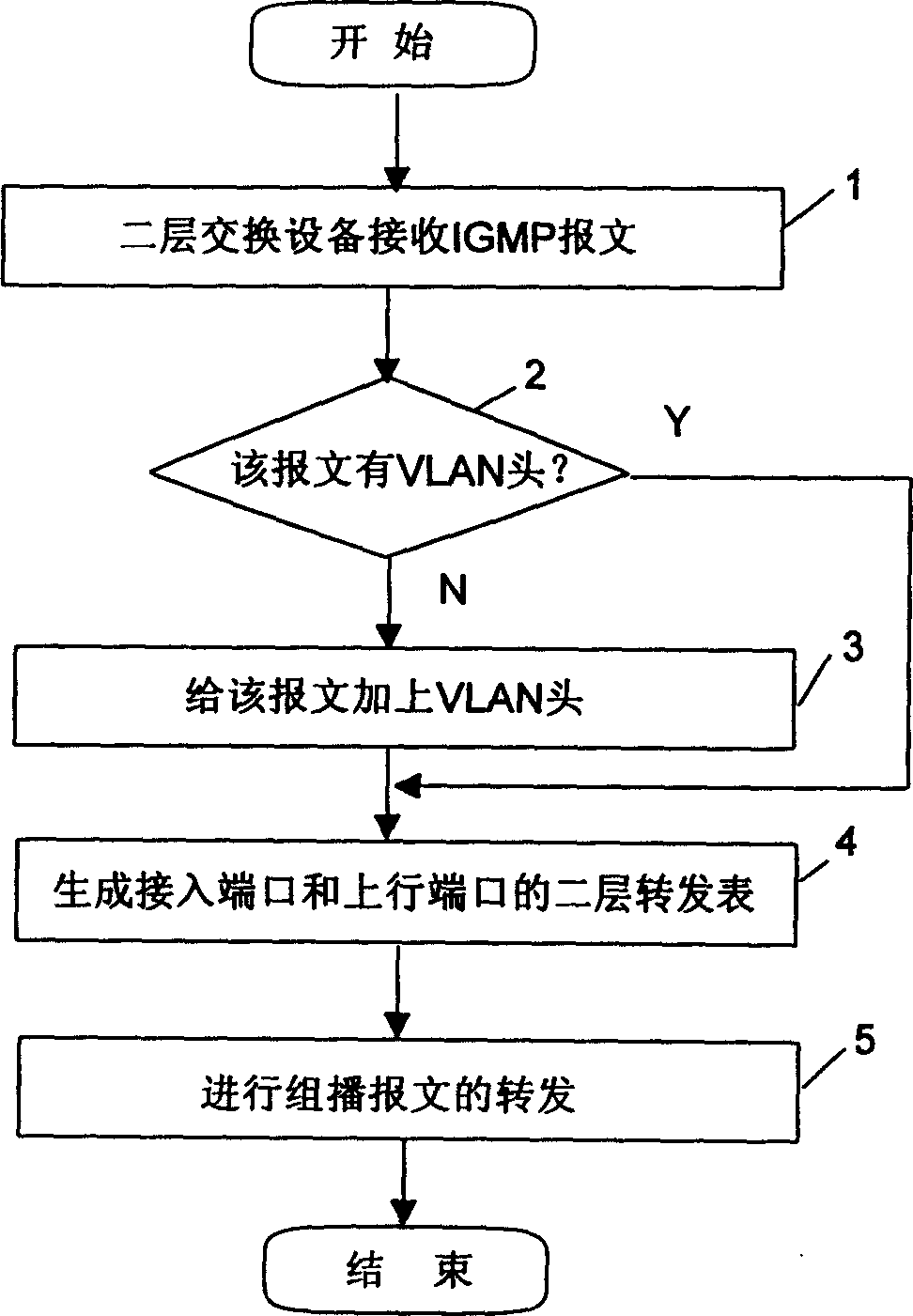
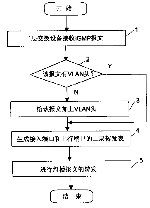
[0012] The present invention will be described in further detail below in conjunction with the accompanying drawings.

[0013] Generally, there are two types of multicast packets processed by Layer 2 switching devices: IGMP packets and multicast data packets. These are two different types of messages, although they both use the multicast MAC address as the destination MAC address: the IGMP message is a signaling control message for the user terminal to notify the network device that a certain multicast service is needed. When a certain multicast service is provided, the corresponding IGMP message will be sent out, and the destination MAC address of the IGMP message and the destination MAC address of the corresponding multicast data message use exactly the same multicast MAC address; while the multicast data message The text is the real data packet carrying the content of the multicast service. Therefore, the generation of the Layer 2 forwarding table of the multicast message ...


PUM


Abstract

This invention discloses a multimessage CC method based on a two-layer exchange device receives IGMP message from the ACC port to judge if there is VLAN head in the message; if not, adding VLANID of the ACC port to the said message to form VLAN head, then to generate an image relationship list of ACC port VLANID and MAC address to IGMP message physical port and generating an image relationship list of up-line port VLANID and MAC address to IG MP message physical port, and finally to the multimessage according to the above image relationship list.

Description

technical field [0001] The invention relates to a message forwarding method in a communication network, in particular to a multicast message forwarding method based on a two-layer switching device. Background technique [0002] Currently, in a broadband network, a user terminal usually accesses the network through a Layer 2 switching device, and the most common Layer 2 switching device is an Ethernet Layer 2 switch (LANSWITCH) supporting the 802.1Q protocol. The following uses LANSWITCH as an example to illustrate the forwarding of multicast packets. All messages sent by user terminals connected to the network by LANSWITCH must be added with a special tag for user terminal identification. In practice, this tag is usually a virtual local area network (VLAN: Virtual Local Area Network) tag. This VLAN The label can uniquely identify the specific physical interface where the user terminal accesses LANSWITCH, that is, the Ethernet format message sent by the user from the access ...

Claims


Application Information

Patent Timeline
IPC IPC(8): H04L45/16
Inventor 张群
Owner HUAWEI TECH CO LTD
Why Eureka
Try Eureka