Data transmission apparatus and data transmission method

A technology of data transmission device and transmission path, which is applied in the direction of digital transmission system, transmission system, data exchange network, etc., and can solve problems such as the increase of sending cells of quality level and the deterioration of communication quality

Inactive Publication Date: 2003-12-31
PANASONIC CORP
View PDF1 Cites 2 Cited by
  • Summary
  • Abstract
  • Description
  • Claims
  • Application Information

AI Technical Summary

Problems solved by technology

[0011] However, the above-mentioned conventional data transmission apparatus has a disadvantage that among a plurality of quality classes, in a quality class in which a marked cell is first detected, the cell cannot is transferred to the transmission path, and this delay results in an increase in the quality level of the sent cell
Specifically, in the case of CBR (Constant Bit Rate), there is a defect that during the period when cells are not transmitted, it is considered that the communication of such a quality level is disconnected, in other words the communication quality deteriorates

Method used


Image

  • Data transmission apparatus and data transmission method
  • Data transmission apparatus and data transmission method
  • Data transmission apparatus and data transmission method

Examples


Embodiment Construction

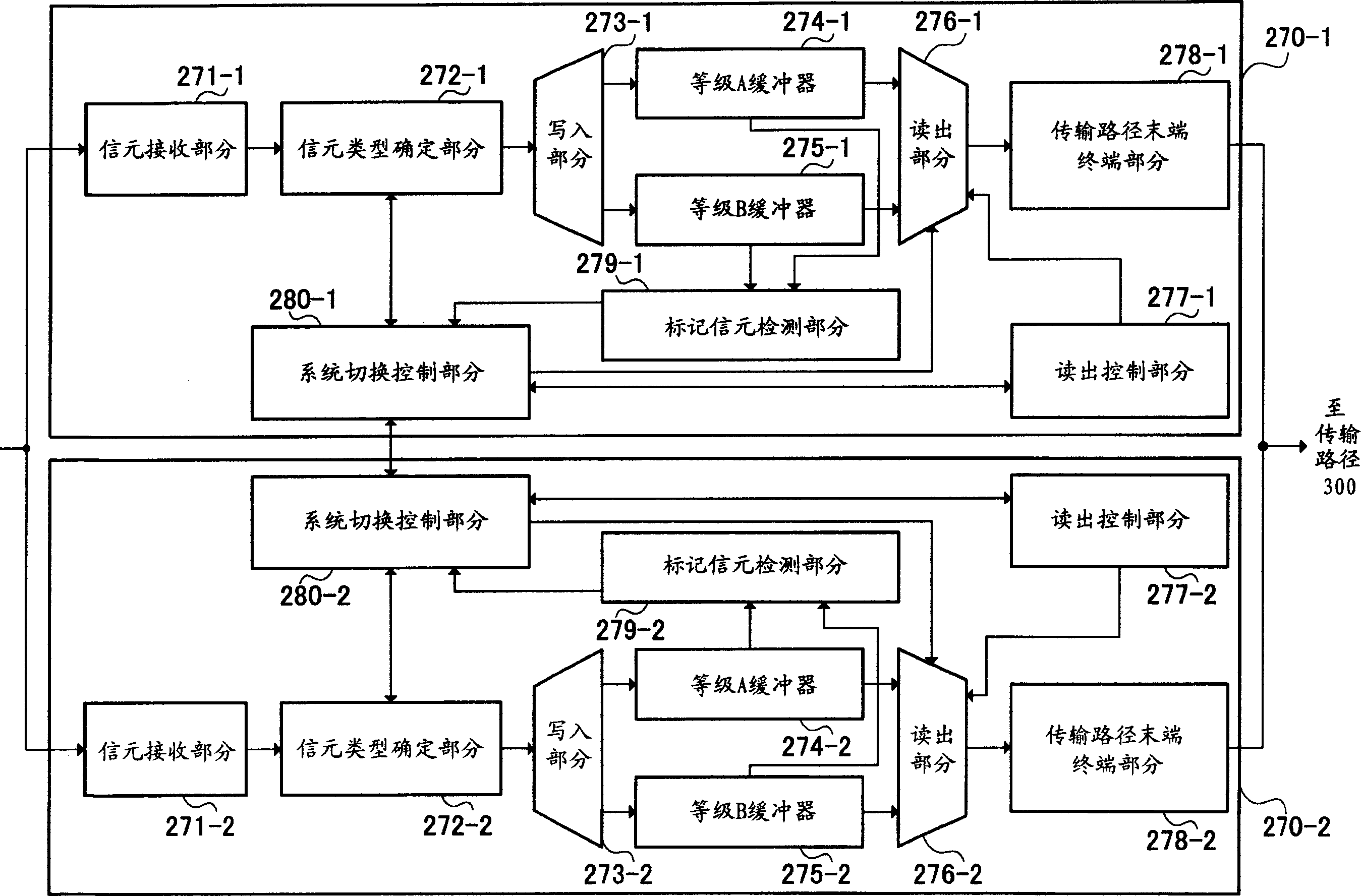
[0024] The gist of the present invention is: when the currently used transmission path interface part receives a marker cell representing the switching time, this part writes a copy (replica) of the marker cell in buffers of all quality levels, and After a marked cell is detected during cell reading in each buffer, until a marked cell is detected in buffers of all quality levels, this part always reads cells from the currently used buffer, corresponding to Cells read from buffers reserved for use are discarded, and when marked cells are detected in buffers of all quality classes, a switch is made between currently used and reserved use.

[0025] Embodiments of the present invention will be described below with reference to the drawings.

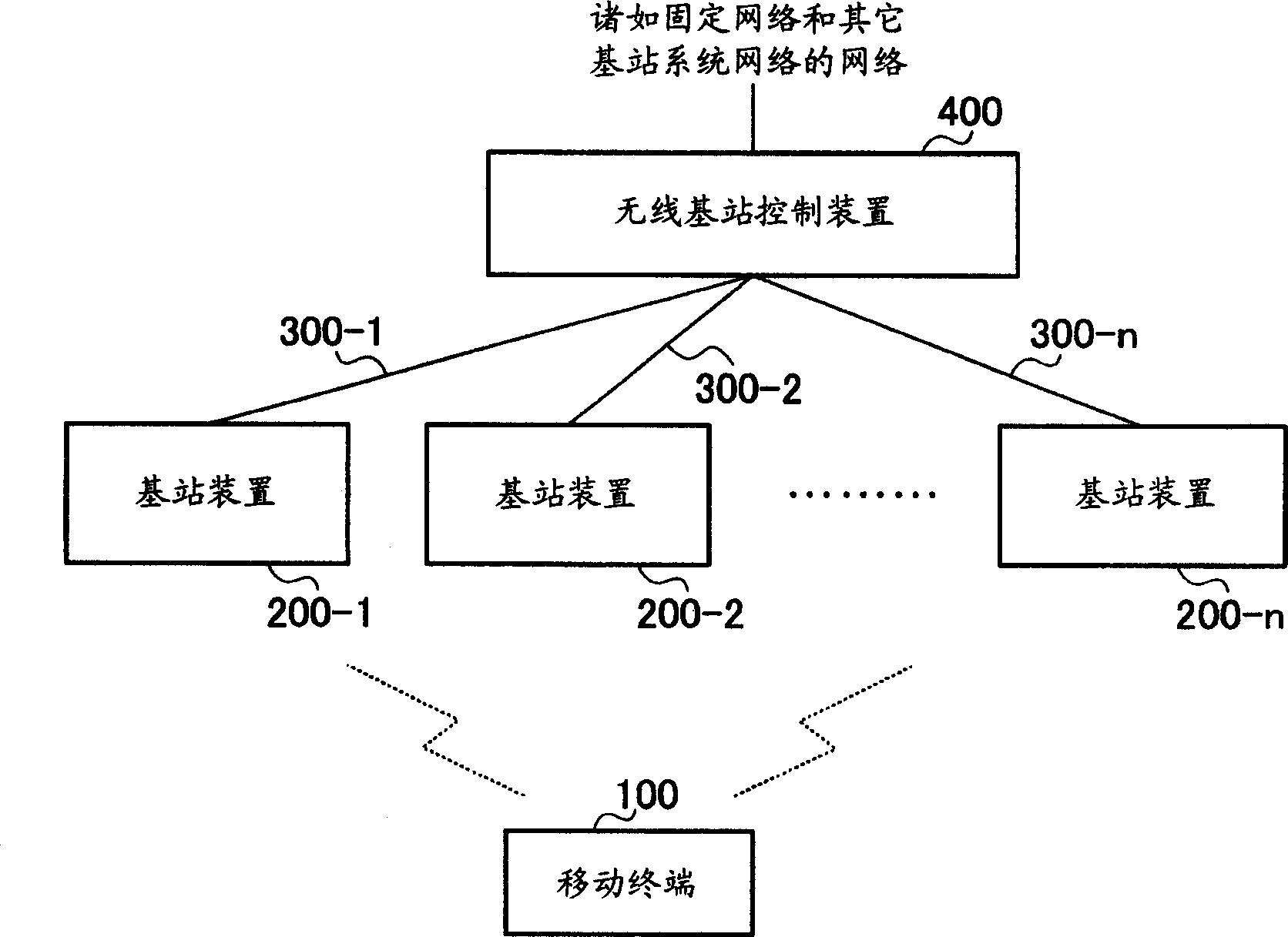
[0026] figure 1 is a block diagram illustrating the configuration of a mobile communication system according to an embodiment of the present invention.

[0027] Such as figure 1 The illustrated embodiment of the mobile communication system...


PUM


Abstract

Upon reception of a marker cell indicating a current/reserved switching timing, a system switching control block (280-1) of a first transmission path interface block (270-1) which is a current system in the initial state notifies contents of a read out order table and a read out pointer to a system switching control block (280-2) of the reserved system. After the marker cell is received, a read out block (276-1) for the current system continues to read out cells in accordance with the read out order table and the read out pointer until the marker cell is detected in buffers of all the quality classes. On the other hand, a read out block (276-2) of the reserved system discards cells in accordance with the read out order table and the read out pointer notified to the system switching control block (280-2). When the marker cell is detected in buffers of all the quality classes of the current system, the current/reserved switching is performed.

Description

technical field [0001] The invention relates to a data transmission device and a data transmission method, which are used for assembling received user data into ATM cell (CELL) for transmission on a transmission path. Background technique [0002] In a data transmission device for transmitting received user data over a network, it is necessary to provide a system with a dual configuration for current use and reserve use in order to improve reliability. In this case, it is necessary to switch between the currently used and the reserved system in an instant. Specifically, it is necessary to design a transmission path interface section for transmitting frames such as ATM (Asynchronous Transfer Mode) cells to the transmission path to prevent loss or overlap of cells. [0003] In the transmission path interface section of the data transmission device, a buffer is provided for each quality level (for example, each connection or a quality level required for connection (such as del...

Claims


Application Information

Patent Timeline
Patent Type & Authority Applications(China)
IPC IPC(8): H04L1/22H04L45/24H04L45/58H04L47/32H04L47/6275
CPCH04L2012/5681H04L41/5022H04L12/5601H04L2012/5651
Inventor 大村正广樋口信一
Owner PANASONIC CORP
Why Eureka
Try Eureka