
Mobile telephone set

A telephone and portable technology, applied in the field of portable telephones, can solve problems such as voice quality degradation and LSI failure.

Inactive Publication Date: 2004-01-21
NEC CORP
View PDF0 Cites 2 Cited by
  • Summary
  • Abstract
  • Description
  • Claims
  • Application Information

AI Technical Summary

Problems solved by technology

In the area defined between the circuit board 4 and the rechargeable battery 2, a large amount of high-frequency current flowing through the circuit board 4 is shunted to an LSI (Large Scale Integration) provided on the circuit board 4, resulting in failure of the LSI
For example, there may be a case where the voice quality in a conversation over the telephone is degraded due to impulse noise in the voice signal, which is generated from a high-frequency current spurious from a circuit board in an LSI constituting a receiving circuit

Method used


Image

  • Mobile telephone set
  • Mobile telephone set
  • Mobile telephone set

Examples


Embodiment Construction

[0018] The following will be combined with Figure 4 An embodiment of the invention is described, Figure 4 is a cross-sectional portion of a mobile phone according to an embodiment of the present invention. For simplicity of explanation, the display portion and operation buttons are omitted.

[0019] exist Figure 4 Among them, the circuit board 4 is a multilayer printed circuit with a ground layer 40 inside. Integrated circuit elements 41 such as LSI are mounted on the circuit board 4 . The circuit board 4 is electrically connected to the antenna 5 and the rechargeable battery 2 . The circuit board 4 and the rechargeable battery 2 are electrically connected to each other through a pair of power supply pins 6 and a plurality of ground pins 8 . In addition, a pair of charging terminals 3 are provided on the rechargeable battery.

[0020] Figure 5 It is a plan view of the battery housing portion 120 of the mobile phone 1 without the rechargeable battery. Ground pins 8 are...


PUM


Abstract

In a portable telephone having a rechargeable battery, an electrically conductive outer cover of the rechargeable battery is connected at a plurality of locations to a ground layer of a circuit board provided within the portable telephone.

Description

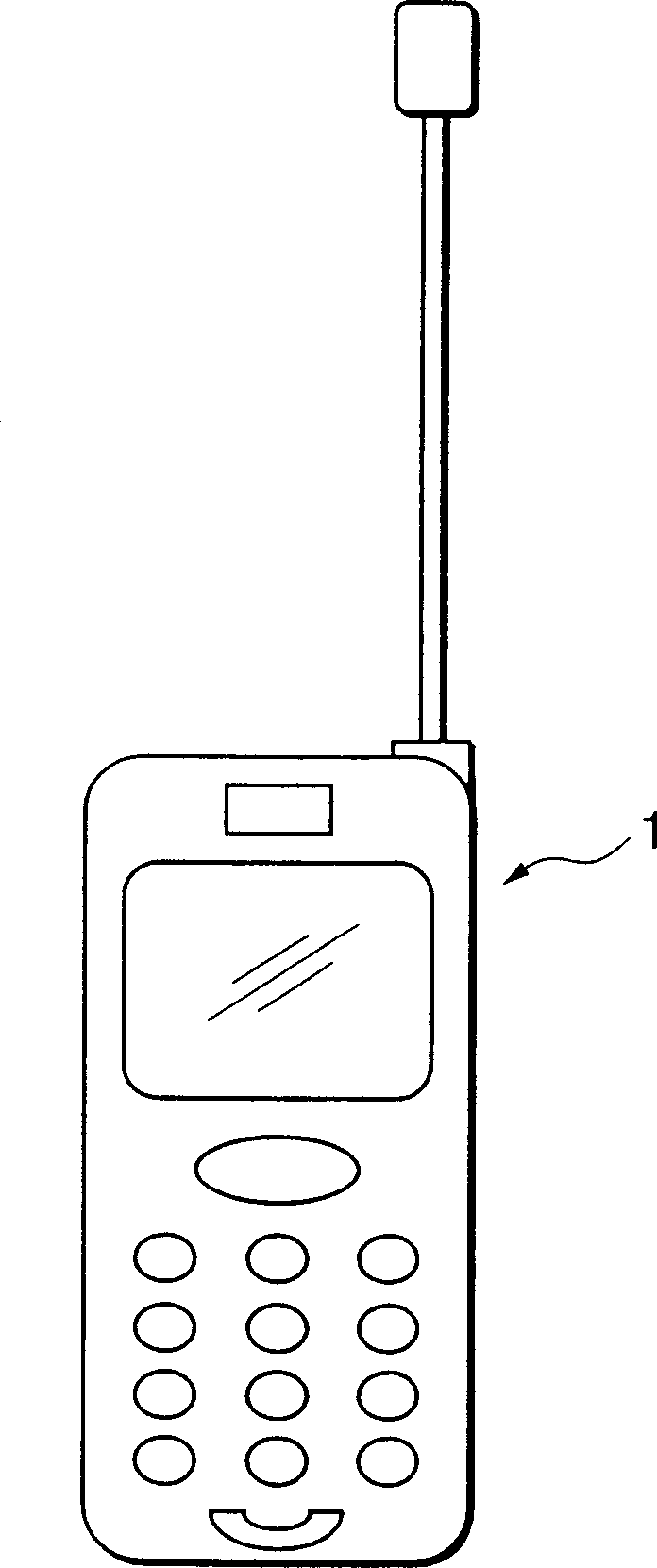
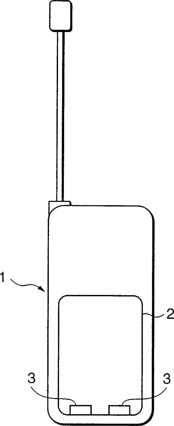
technical field [0001] The present invention relates to portable telephones, and more particularly to portable telephones having a rechargeable battery as a power source. Background technique [0002] A conventional portable phone or cellular phone having a rechargeable battery as a power source will be described with reference to FIGS. 1A, 1B, 2 and 3. Referring to FIG. Fig. 1A is a front view of a conventional portable telephone and Fig. 1B is a rear view thereof. A rechargeable battery 2 having a charging terminal 3 is attached to the back of the mobile phone 1 . [0003] Fig. 2 is a cross-sectional view of the mobile phone shown in Figs. 1A and 1B. A rechargeable battery 2 is provided in the housing of the body of the portable telephone 1 and supplies power through a pair of power supply pins 6 to a circuit board 4 (such as a multilayer printed circuit board) including a radio circuit disposed therein. , receiving circuit, transmitting circuit and control circuit and ...

Claims


Application Information

Patent Timeline
IPC IPC(8): H04M1/02H01Q1/52H04B1/38H05K9/00
CPCH01Q1/526H05K9/0039H04B1/3838
Inventor 栗山敏秀半杭英二小林直树山下正义
Owner NEC CORP
Learn More